|
|
| GERMAN EXPLOSIVE ORDNANCE - BOMBS, BOMB FUZES, ROCKET, LAND MINES, GRENADES AND IGNITER |
| Chapter 1 |
| GERMAN BOMBS |
| AB 250-1 CONTAINER |
| DATA: |
| Over-all Length: 64 1/4 in. |
| Body Diameter: 15 1/8 in. |
| Wall Thickness: 3/32 in. |
| Filling: 96 SD 2 bombs. |
| Fuzing: Z 69 D. |
|
CONSTRUCTION. The container consists of a center beam to which are attached three pairs of semicircular casings. The whole forming a cylinder bi-sected verti-cally by the center beam. |
|
The center beam is composed of two mild steel pressings, welded together to form, in cross section, an octagonal tube extending to an upper and a lower double-sheet web which open at their extremities to form V-channels. The upper and lower channels are reinforced by pressings welded within the V-channels. |
|
Spaced within the octagonal tube are four pairs of octagonal plates, grooved at right angles on their inner faces. When fitted together, the grooves correspond and make interconnected radial tubes in the form of a cross. |
|
Holes drilled in the center beam correspond with each horizontal tube. Extensions to the vertical tubes are formed within the upper and lower webs. Guide plates centrally drilled are spaced within each lower vertical tube. |
|
The holes cut in the wall of the center beam accommodate the arming cables of the SD 2 bombs. |
|
Distance pieces are fitted to the external faces of the central beam. |
|
A release plate hinged at its forward end is fitted to the outside of each casing. |
|
A small slot cut in the release plate corresponds with a similar slot cut in each casing. |
|
Bomb positioning ribs are welded to the inner face of each casing. |
|
After loading the container, the holes cut in each casing permit the withdrawal of the bomb safety clips. The nose fairing and the tail dome are formed by welding metal pressings to the front and rear pairs of casings respectively. The charging adapter is screwed to a small stud plate fitted within the upper channel. The sus-pension lug platform, containing the suspension lug housing, is welded to metal arms riveted to the walls of the upper channel. |
|
The lateral guides within the lower channel, form seatings for the bracket of the front, central and rear release rods. The steel link rods are formed with "eyes" at each end. The inner eye enters a horizontal tube, in which position the appropri-ate release rod passes through the eye, thereby securing the link rod. The outer eye passes through the slots in the casing and release plate and is secured on the outside by a steel split pin. Double compression springs are fitted in the lower vertical tube between the guide plate and the release rod bracket. The base pla-te of the fuze pocket is secured within the lower channels by means of two nuts and bolts. |
|
A fuze pocket and enclosed spring loaded electric terminal are secured to the base plate by two screws. A steel circlip around the fuze provides the negative contact for the circuit. |
|
One red covered and one yellow covered cable enclosed within a red waterproof cover complete the electric circuit between the charging adapter and the fuze assembly. |
|
A strong steel sleeve with a threaded steel cap, is a sliding fit over the fuze poc-ket. The threaded steel cap is fitted with a small circular polystyrene window for visually checking the presence of the fuze. |
|
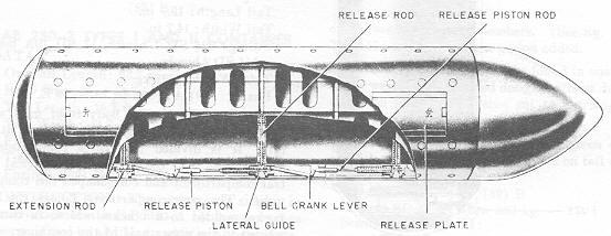
One extension rod passes through the front lateral guide and front release rod bracket, thus retaining the front release rod. |
|
The longitudinal bracket forms a guide for the release piston. The release piston rod, passing through the central lateral guides, retains the central release rod. The release piston springs are compressed between a sealing machined on the release piston rod and the central lateral guide. |
|
The bell crank lever pivoted in the longitudinal bracket has a small metal plate la-terally attached to its long arm. The nose of the bell crank lever, passing through the longitudinal bracket, retains the release piston. The notched plate at the tail of the bell crank lever being retaining by the extension rod prevents the rotation of the bell crank lever. A similar mechanism to the rear of the central release rod provides for the operation of the rear release rod, the exception being that the rotation of the second bell crank lever is prevented by the release piston rod. (See fig. 105.) |
|
OPERATION. On release from aircraft, the fuze fires after the approximately 1-second delay propellant charge is ignited. Pressure drives the steel sleeve down-ward, the steel sleeve extension, and extension rod. The extension rod disenga-ges from the front release rod bracket. The front release rod under the influence of its spring moves downward and fires the link rods. Airflow passing under the release plate causes to move outward, thus firing the bombs. This movement is assembly by the weight of bombs and the tendency of the drogues to spring open. The first bombs then fall away. As the extension rod moves forward, it is also disengaged from the notched plate at the tail of the bell crank lever. |
|
The bell crank lever is now free to rotate and the release piston moves forward under the influence of its springs and bears on the nose of the bell crank lever rotating it out of the piston guide. This release the piston rod bracket, thereby releasing the central casing. The rear casings are now freed in a similar manner. The small plate on the bell crank lever appears to prevent the simultaneous relea-se of the casings. On release of the first pair of casings, the bell crank lever ro-tates until the small metal plate bears against the casing. The bell crank lever is now unable to rotate further until the front casings are clear of the lower chan-nel. This momentarily delays the release of the second pair of casings. This ser-ves to increase the scatter of the bombs. |
|
Figure 105 – AB 250-1 Container |
|
|
|
|