|
|
| LAND MINES |
| Section V |
| FUZES AND FIRING MECHANISMS |
|
26. PRESSURE FIRING DEVICE M1. |
|
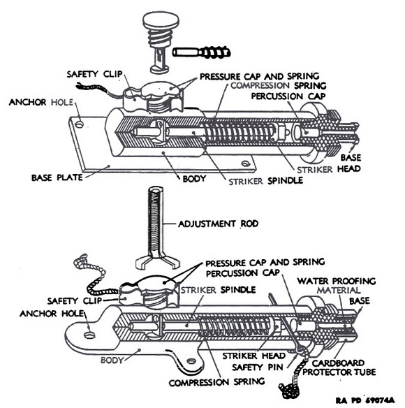
a. Description. The Pressure Firing Device M1 (produced from Corps of Engineers) is a nonelectric device designed to cause the detonation of antipersonnel mines or other ex-plosive charges when the device is subjected to a pressure of 30 pounds or more. The device (figs. 18 and 21) is mounted on a rectangular metal base plate, measuring 2½ by 1½ inches, and is composed of a barrel, head, and base. The barrel contains the firing mechanism and a safety pin. The head, permanently joined to the barrel, contains the trigger assembly. The base, which screws into the barrel, contains a recess into which a percussion cap fits and a projection over which a nonelectric blasting cap is crimped. (The base and percussion cap are identical with those used on the Pull Firing Device M1.) The firing mechanism consists of a striker assembly, a striker spring, a trigger assembly, and a trigger spring. The striker assembly consists of a round spindle, with a groove three-eights of an inch from the end opposite the striker, the striker head, and a firing pin mounted on the striker head. The trigger unit consists of a large, flat head, flat head mounted on a trigger pin extending through the side and down into the barrel. The trig-ger pin has a pear-shaped hole in it. The small section of the spindle fits in the small end of a pear-shaped hole so that the striker spring is unable to cause movement of the striker and firing pin. A safety clip extends around the trigger pin, between the barrel and the trigger head. No appreciable movement of the trigger pin against the action of the trigger spring is possible until the safety clip is removed. The firing pin is restrained from striking the percussion cap until the safety pin through the body is removed. |
|
b. Functioning. When the safety clip is removed, a force of from 25 to 35 pounds applied to the trigger head through a distance of three-sixteenths of an inch is sufficient to overcomes the resistance of the trigger spring and cause the trigger pin to move into the barrel, permitting the striker and firing pin to be driven forward and strike the percus-sion cap. The percussion cap detonates a nonelectric blasting cap crimped to the pro-jection on the base. |
|
|
|
Figure 21 - Pressure Firing Device M1 |
|
c. Installation. To install the Pressure Firing Device M1, the procedure is a follows: |
|
(1) Prepare and place the mine charge as for the combination firing device (par. 24) |
|
(2) Keeping the safety clip in position on the firing device, remove the base containing the percussion cap. |
|
(3) Place the firing device in position at the location where it is to be used. Be sure that it has solid footing. Place the pressure device in place and see that it does nor bear too heavily on the trigger head. |
|
(4) Slide the open end of the nonelectric cap around the projection on the base, and crimp, using the cap crimper. |
|
(5) Screw the base, blasting cap attached, to the device. |
|
(6) Prime the charge. When primacord is used, tape the looped end ot the primacord to the blasting cap in the proper manner and run the other end to the charge. If primacord is not used, insert the blasting cap into a block of explosive. |
|
(7) Next remove the safety clip gently. The safety clip should pull off very easily; a sudden jerk may cause the device to fire prematurely. If the safety clip does not pull off easily, check the installation to make sure that there is no pressure on the trigger pin. |
|
(8) The final operation, after all parts of the installation have been checked, is to re-move the safety pin. When the device is firmly anchored, it is good practice to remove safety clip and safety pin from a safe distance, using a string or length of wire for the purpose. |
|
(9) When the firing devcie is employed with the Fragmantation Hand Grenade Mk II, un-screw the grenade fuze assembly without removing the safety pin. Utilize the fiber washer under the fuze head assembly by placing it under the flange of the firing device base. Screw the firing device base, with nonelectric blasting cap attached, back into the grenade in place of the fuze assembly. Place the grenade, with firing device attached, and carefully camouflage the installation. |
|
d. Packing. These firing devices are packed in boxes containing five devices each, complete with percussion caps. A full box weighs 1 pound 14 ounces, and measures 4¾ by 1 5/8 inches. |
|
|