|
|
| GERMAN MINE WARFARE EQUIPMENT |
| PART TWO – GERMAN MINE WARFARE EQUIPMENT |
| CHAPTER 9 - MINE DETECTING EQUIPMENT |
| Section III. ELECTRICAL - ACOUSTIC MINE DETECTING DEVICES |
|
140. Vibration Detector |
|
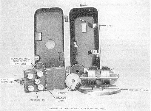
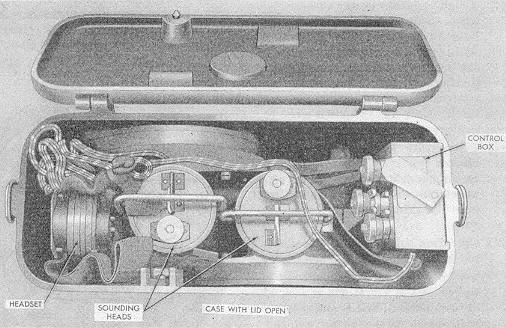
a. General. The vibration detector (fig. 181) can be used to detect underground tunnel-ing operations, to operate as an acoustic mine obstacle, and to detect radio detonated, remote controlled mines and mines set with clock-work delay fuzes. |
|
Figure 181. Vibration detector. |
|
|
|
|
|
b. Description. The complete apparatus (fig. 181) is housed in a black cast-metal case of extremely strong and moisture-resistant construction. It consists of two sounding heads, a control box, a 40-ohme headset, and a 4 1/2-volt dry cell battery. |
|
(1) |
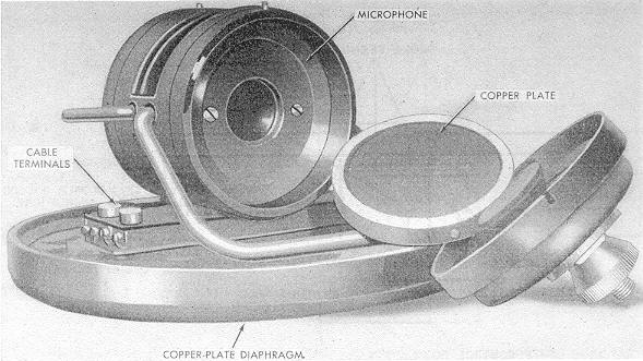
Sounding head. Each sounding head (fig. 182) has a horizontal copper plate dia-phragm, 5 1/2 inches in diameter. Its vibrations are are transmitted through a verti-cal air column to a double-button microphone. Each button has resistance of about 200 ohms. The sounding head weighs about 5 pounds and is 3 3/4 inches high and 5 3/4 inches in diameter at the widest part of the base. Two terminals are provided for connecting by cable to the control box. |
|
Figure 182. Sounding head for the vibration detector. |
|
|
|
(b) |
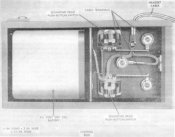
Control box. The wooden control box (fig. 183) contains the headset, which is per-manently attached to the box, and the battery. The total weight, including the head-set and the battery is about 1 pound. The box is 6 inches long, 3 inches wide, and 1 1/2 inches high. It is equipped with three cable terminals, the center one being a common return for both sounding heads. Two white push buttons enable the sounding heads to be used independently of each other. |
|
Figure 183. Interior of the control box. |
|
|
|
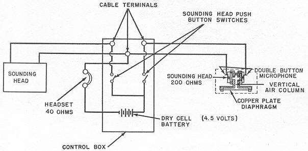
c. Wiring. The two sounding heads are connected in parallel to the control box where they are joined in series circuit with the battery and the headset through the white push-button switches (fig. 184). |
|
Figure 184. Wiring diagram of a vibration detector |
|
|
|
|