|
|
| GERMAN MINE WARFARE EQUIPMENT |
| PART TWO – GERMAN MINE WARFARE EQUIPMENT |
| CHAPTER 9 - MINE DETECTING EQUIPMENT |
| Section III. ELECTRICAL - ACOUSTIC MINE DETECTING DEVICES |
|
135. General |
|
During World War II the German Army developed and employed equipment designed to detect activities by amplified vibrations in the ground. In some instances an electrical circuit for detonating mines by remote control was used in conjunction with these detec-tion devices (par. 136). Althrough originally designed to detect tunneling activities, much of this acoustic equipment was used satisfactorily to detect other activities such as the movements of vehicles and foot troops. |
|
136. Mine-Gallery Detector Set 40 (Stollenhorchgerät 40) |
|
a. General. The mine-gallery detector set 40 is used to detect tunneling activities of an opposing force and to locate them by application of surveying methods. Vibrations picked up by the detector heads can be transmitted a maximum of 660 to 1,650 feet to the control post, where they are identified by trained operators. |
|
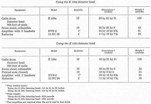
b. Component parts (table I). |
|
(1) |
Detector heads. Two types of detector heads may be used with the mine-gallery detector set 40. They are the E 105a and the 105c. Detector heads are piezoelec-tric receivers of ground vibrations. Since the electrical currents generated in the receiver are extremely small, a pre-amplifier in the detector-head unit amplifies them. The connection bet- ween the detector-head unit and the amplifier unit EVB 6 is made by a shielded four-core rubber detector-head cable. During shipment, the detector head is placed in the hollow axle of the cable drum. The E 105a detector head is held in this position by a tape, and the E 105c by a spring-loaded snap fas-tener which engages the carrying-handle lug. |
|
(a) |
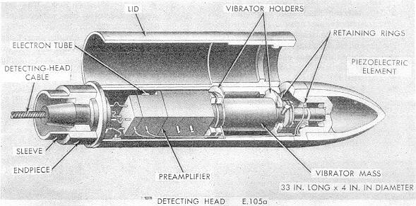
E 105a detector head. The E 105a detector head (fig. 164) is a projectile-sha-ped unit, 33 inche long and 4 inches in diameter, designed for use in bore ho-les. It has a slightly narrowed sleeve at the rear, and a length of cable perma-nently connected to it. The piezoelectric element is located in the nose end and is held in place by retaining rings. Immediately behind the piezoelectric ele-ment is the vibrator mounted on the vibrator holders. The preamplifier, with the electron tube, is connected to the vibrator and the endpiece. |
|
Table I. Component Parts of the Mine-Gallery Detector Set 40. |
|
|
|
Figure 164. E 105a detector head. |
|
|
|
|
|
(b) |
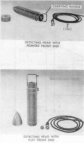
E 105c detector head. The E 105c detector head (fig. 165) has the same sha-pe as the E 105a, but does not have a sleeve. The pointed front end is remo-vable and can be replaced by a flat endpiece. In place of the sleeve, a carry-ing handle, with the contact socket for the detector-head cable beneath it, is fitted to the rear end. The contact socket is protected by a screw cap, which should not be removed until the detector-head cable connection is laid out and prepared for insertation. |
|
Figure 165. E 105c detector head. |
|
|
|
(2) |
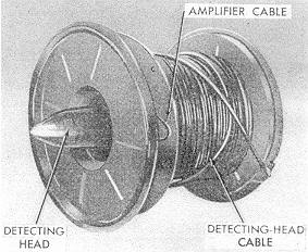
Cables and cable drums (fig. 166). The cable drum has two winding compartments separated from each other by a pressed-steel disk. The main lenght of detector-head cable with the end connector for the detector head is wound on the larger space. The smaller space has room for approximately 50 feet of cable with the plug connecter for the EVB 6 amplifier. |
|
Figure 166. Cable and drum showing the carrving place for the detector head. |
|
|
|
(3) |
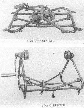
Cable-drum stand. The cable-drum stand (fig. 167) facilitates winding and unwind-ing of the cable. It is collapsible and is made of tubular steel with a guide disk and a clutch for manual operation. |
|
(4) |
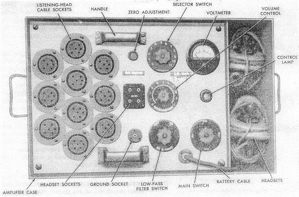
EVB 6 amplifier. The EVB 6 amplifier unit (fig. 168 and 169) is fitted into a shipping case of plywood reinforced by thin sheet metal. It consists of the followings parts: |
|
(a) |
The front plate contains 10 sockets arranged in a honeycomb pattern on the left half of the palte. The sockets are for the connection of detector heads. The operation and control connections are fitted on the right. The selector switch, on the top of the front plate, provides a connection with any one of the 10 detector heads. Underneath the selector switch is a volume control and, below that, the switch for the low-pass filter (200 cycles per second). A voltmeter to the right of the selector switch indicates the battery voltage du-ring operation of the amplifier unit. The connection between the amplifier unit and battery is made by a short length of battery cable leading out of the front plate. The control lamp, beneath the voltmeter, lights when the amplifier unit is switched on. The main switch for the unit is situated at the bottom right cor-ner of the front plate; the sockets for the headsets are in the center of the plate. The zero adjustment (just above the headset sockets) is to be regulated only by specially trained personnel. The shielding lead in the shielded head-sets must always be plugged into the ground socket, immediately below the headset sockets. |
|
|
(b) |
Two headsets are kept in the side compartment of shipping case. |
|
|
(c) |
The triangular box spanner fits the bolts which hold the amplifier front plate by its four corners. These bolts are unscrewed to remove the amplifier unit from the shipping case. The spanner is kept in the side compartment of the shipping case. |
|
Figure 167. Cable-drum stand. |
|
|
|
(d) |
The spare-parts box contains one vibrator, one stabilizer electron tube, one space bulb for the control light, and one fuze. Three additional space electron tubes are mounted inside the amplifier unit itself. The spare-parts box is kept in the side compartment of the shipping case. |
|
(5) |
12 NC 28 battery. One 12 NC 28 battery is required for the operation of the 10 de-tector heads and the amplifier unit. This battery has an average voltage of 12 volts and a capacity of 28 ampere-hour. |
|
c. Functioning. Ground vibrations received by the detector heads are trans-formed into electrical impulse and are transmitted to the amplifier EVB 6 where they are made audible through the headsets. |
|
d. Use in the Field. |
|
(1) |
On the surface of the ground. |
|
(a) |
Two men are required to set up the control post in the field. When the amplifier case has been opened and all the connections made, a slight hum, originating from the vibrator, can be heard in the headset. The heating period for the electron tube is approximately 30 seconds, after which the set is ready for operation. |
|
|
(b) |
The oscillator circuit must be inserted when the operator is listening for tunnel-ing vibrations. This is indicated by a slight vibration which is audible when the set is on. |
|
|
(c) |
To test the detector heads before use, slide a hand over the detector head. A slight rustle should be heard through the headset. |
|
|
(d) |
Two men can fix the cable-drum stand to the drum, or demount it from the drum. Three men are required to unwind cable from the drum and to bring the detector head to its forward position. |
|
Figure 168. EVB 6 amplifier. |
|
|
|
(e) |
The detector-head cable should be concealed and if possible, laid in ditches or along hedgrowes. If the cable is laid in open country, particular care must be taken in camouflaging it. In trenches, detector-head cables are fixed on the side toward the opposing force by means of wooden pegs or iron clamps. |
|
|
(f) |
A hole 7 feet deep is requried for each detector head to obtain a good detect-ing range with a comparatively small amount of interference noises. |
|
|
(g) |
After the detector head has been placed, it is checked to see that it makes a good solid contact with the surrounding soil. |
|
|
Caution: The detector head may have antilifting devices attached (par. 114). |
|
(2) |
Underground. |
|
(a) |
When the mine gallery detector set 40 is used underground in a mine or tunnel, the detector heads are placed in bore holes dug with a mine boring machine. The setting up of the control post and use of cable drums and stands remain the same as for surface use. To obtain bearings, however, it is necessary to listen in on two detector heads simultaneously and to compare their reactions. A detecting control of this type consists of two harmonized amplifier and two batteries. Of each pair of detector heads to be compared, one detector head is connected to each amplifier unit. The headsets are connected with one headset plugged into each amplifier. The system should be checked to see that both detector heads give identical reactions under similar conditions. |
|
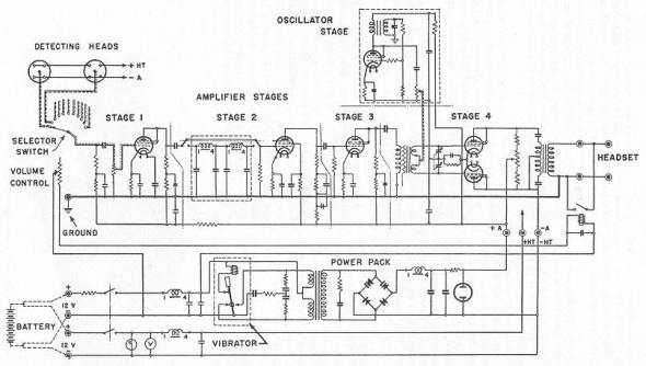
Figure 169. Wiring diagram for the EVB 6 amplifier. |
|
|
|
(b) |
To place the E 105a detector head in a bore hole, the sleeve is fixed to the end of the bore-washing tube. When the detector head is in position, the tube should be disonnected and withdrawn approximately 3 feet; only then is the detector head able to pick up the vibrations in the soil surrounding it. |
|
|
(c) |
Different types of soil produce a wide variation in ranges. Before actual opera-tion, a range test should be undertaken, wherever possible, in the particular type of soil to be encountered. For this test, the detector heads should be placed at 30-foot intervals, one at 30 feet from the source of the test vibra-tions, the next at 60 feet, and so on. The detector heads are then checked, one after another. The average range determined for the particular type of ground will be that range at which the source can be discerned without doubt at the medium stage of amplification. |
|
|