|
|
| GERMAN MINE WARFARE EQUIPMENT |
| PART TWO – GERMAN MINE WARFARE EQUIPMENT |
| CHAPTER 7 - ANTIPERSONNEL MINES |
| Section I. ANTIPERSONNEL MINES |
|
101. Ice Mine or Bottle Mine 42 (Flascheneismine 42; Fl.Es.Mi. 42; Also, Erschüt-terungsmine) |
|
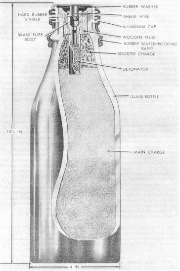
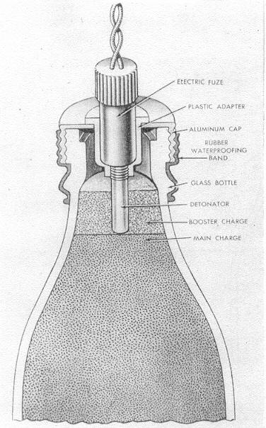
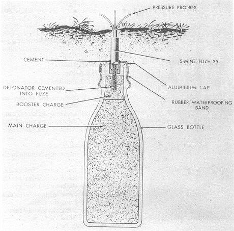
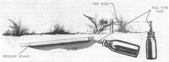
a. Description. The antipersonnel ice mine or bottle mine 42 (fig. 120 and 121) resembles a quart-site milk bottle. It has a thick-glass body, 10 1/2 inches high and 4 inches in dia-meter, filled with about 4 pounds of explosive. A booster charge is located in the neck of the bottle. A wooden plug fits into a recess inside the mouth. The wooden plug holds an impact fuze which has a detonator crimped to its base. An aluminum cap, waterproofed with sealing compound, screws on the top of the bottle over the fuze. A rubber water-proofing band fits over a portion of the alumnium cap and glass bottle. The impact fuze used in this mine is designed to function under the concussion of a nearby underwater explosion. An ice mine fitted with an electric fuze is used as the initiating mine to set off the explosion which detonates the nearest impact-fuzed ice mine. In the initiating mine, the aluminum cap covering the top of the mine has a built-in, threaded, central fuze well for insertion of the electric fuze. Sealing compound is placed around the electric fuze and aluminum cap. The S-mine fuze 35 (fig. 122) and the pull fuze 42 (fig. 123) are some-times used in this mine. |
|
Figure 120. Ice mine of bottle mine 42. |
|
|
|
b. Employment. |
|
(1) |
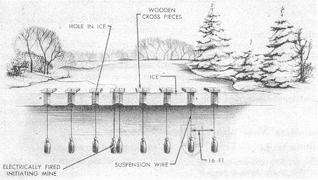
Althrough this mine was used by the Finnsih army in winter warfare to create water obstacles by blowing gaps in the ice on rivers and lakes (TM 5-223B), the German Army adopted it and employed it as an antipersonnel mine as shown in figures 122 and 123. The mine was orignally designed to be elft in the water under ice and be detonated by remote electrical control at the approach of personnel. Ice mines are normally laid in frozen rivers or lakes in rows or "fields". They are suspended through holes in the ice, 6 feet below the surface, by means of wires attached to wooden cross pieces placed over the holes (fig. 124). They are normally spaced about 16 feet apart. |
|
(2) |
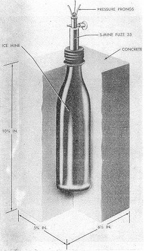
The ice mine may also be encased in a block of concrete to add shrapnel effect for antipersonnel use. In this case, it may be fitted as shown in figure 125. |
|
c. Functioning. |
|
(1) |
Impact fuze. When the initiating mine with the electric fuze detonates, the concus-sion travels through the water to the nearest impact-fuze mine, shearing the shear wire in the impact fuze and releasing the spring-loaded striker against the percus-sion cap, firing the impact-fuzed mine. The concussion from the detonation of the first impact-fuzed mine causes the next impact-fuzed mine to detonate and so on. |
|
(2) |
S-mine fuze 35 (par. 25). |
|
(a) |
Pressure of 15 pounds on the pressure prongs overcomes the resistance in the plunger spring and depresses the plunger. |
|
|
(b) |
The two striker-retaining balls are forced outward, releasing the spring-loaded striker against the percussion cap and firing the mine. |
|
(3) |
Pull fuze 42 (par. 42). This fuze functions by either pressure, pull, or tension relea-se. |
|
(a) |
Pressure. Pressure of 6 to 11 pounds on the wings of the striker- retaining pin pushes the pin out of the striker shaft, releasing the spring-loaded striker against the percussion cap and firing the mine. |
|
|
(b) |
Pull. A pull from of from 6 to 11 pounds on a trip wire attached to the loop in the striker-retaining pin pulls out the pin, releasing the spring-loaded striker against the percussion cap and firing the mine. |
|
|
(c) |
Tension release. Cutting or breaking a taut trip wire attached to the outer hole in the striker shaft releases the spring-loaded striker against the percussion cap and fires the mine. |
|
Figure 121. Initiating ice mine. |
|
|
|
Figure 122. Ice mine fitted with S-mine fuze 35. |
|
|
|
Fiugre 123. Ice mine fitted with pull fuze 42. |
|
|
|
d. Installing and Arming. |
|
(1) |
Impact fuze. |
|
(a) |
Place the fuze and the attached detonator into the fuze well. |
|
|
(b) |
Screw on the aluminum cap and place the rubber waterproofing band as india-cated in figure 120. |
|
|
(c) |
Place the mine in position. |
|
(2) |
S-mine fuze 35. |
|
(a) |
Attach the fuze, with detonator, to the mine. |
|
|
(b) |
Place the mine in the ground with just the pressure prongs above ground. |
|
|
(c) |
Unscrew the retaining nut from the end of the safety pin and withdraw the safety pin. |
|
(3) |
Pull fuze 42. |
|
(a) |
Pressure. Screw the fuze, with detonator, into the mine. Turn the striker shaft so the wings of the striker-retaining pin are below the striker shaft. This will permit the pin to be pushed out when pressure is applied. |
|
|
(b) |
Pull. Attach a slack trip wire to the loop of the striker-retaining pin after the mine is laid, and fasten the other end of the trip wire to a stake or bush. |
|
|
(c) |
Tension release. With the striker-retaining pin still in the striker shaft, attach a taut trip wire to a stake or bush and then to the trip wire hole in the striker shaft. Be sure the trip wire is taut. Remove the striker-retaining pin with rope or wire from a minimum distance of 50 yards. |
|
e. Neutralizing. |
|
(1) |
Impact fuze. |
|
(a) |
Pull the mine up through the hole in the ice. |
|
|
(b) |
Remove the rubber waterproofing band. |
|
|
(c) |
Unscrew the aluminum cap and lift out the fuze and detonator. |
|
|
(d) |
Remove the detonator from the fuze. |
|
(2) |
S-mine fuze 35. |
|
(a) |
Insert a safety pin in the safety-pin hole. |
|
|
(b) |
Search for, investigate, and cut all slack trip wires connected to the striker-retaining pin. |
|
|
(c) |
Remove the fuze and detonator from the mine. |
|
|
(d) |
Remove the detonator from the fuze. |
|
(3) |
Pull fuze 42. |
|
(a) |
Pressure. Unscrew the fuze and detonator from the mine and remove the deto-nator from the fuze. |
|
|
(b) |
Pull. Search for, investigate, and cut all slack trip wires connected to the stri-ker-retaining pin; then unscrew the fuze and detonator from the mine and re-move the detonator from the fuze. |
|
|
(c) |
Tension relase. Insert a striker-retaining pin or a cotter pin in the inner-most hole in the striker shaft; then cut the taut trip wire, after inverstigating the other end. Unscrew the fuze and detonator from the mine and remove the de-tonator from the fuze. |
|
|
Caution: If the striker-retaining pin is not firmly seated in the striker shaft, the mine should be destroyed in place. |
|
Figure 124. Row of ice mines under ice. |
|
|
|
Figure 125. Ice mine encased in a block of concrete. |
|
|
|
|