|
|
| GERMAN UNDERWATERS ORDNANCE MINES |
| Chapter 12 - CLOCKS AND ASSOCIATED DEVICES |
| AUTOMATIC LATITUDE-ADJUSTMENT DEVICES (A.L.A.) |
| MAGNETIC A.L.A. |
|
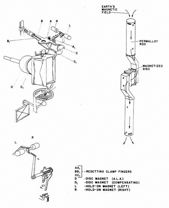
This mechanism consists primarily of two permalloy rods, offset and made into pole pieces with a magnetized spider or disc on a vertically oriented pivot between them. (See figure 300.) Figure 300 shows the adjusting magnets D and D1, which are fitted to concentric shafts. Rotation of these magnets is controlled by the clockwork escapement (figure 299). |
|
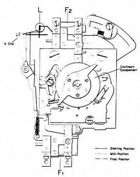
Prior to operation, fuse No. 1 holds the lower arm against spring tension and the arm in turn holds the spring-loaded V-clips arm in at the top. Fuse No. 2 also holds a spring-loaded arm in the upright position. The needle extension arm lies between two sets to rotate toward the contact and hold-on magnet (L) on the left side. This is due to the vertical erath's field which is fed to the needle arm through the vertical pole pieces. |
|
When F1 blows, the A.L.A. escapement starts and the V-clip moves to mid-position; i.e. it restrains the needle extension arm on the RED (left) side only. The escapement ro-tates magnet D and, in so doing, introduces a constantly increasing component of its field into the pole pieces around the needle body. This component is BLUE and tends to counteract the earth's field. |
|
When a point of equilibrium between the two magnetic fields is reached, the needle extension no longer bears against the V-clip, and, since the escapement continues to run, an excess BLUE field is brought to bear on the needle, carrying it over to the BLUE (right) contact. When contact is made, F2 blows, and the following operations are per-formed almost simultaneously: |
|
1. The spring-loaded arm is released and flies to its limit stop, figure 299. |
|
2. The A.L.A. escapement stops and magnet D stops rotating. D1 is rotated by the spring-loaded arm a sufficient amount to remove the excess BLUE magnetic field on the needle. |
|
3. The resetting clamp point BB1, are freed and fly apart as a result of the action of the spring which pulls AA1 together and snaps the needle extension arm to the center. |
|
The needle is now in mechanical and magnetic equilibrium. Rotation of the resetting cam is controlled by a separate escapement in the M 3 unit and by the P.D.M. assembly in the M 3. This rotation will separate clamp points CC1 and thus free the needle arm by spreading of AA1. |
|
Figure 299– Magnetic
A.L.A., Showing Clockwork Escapement and |
|
|
|
Figure 300 – Magnetic A.L.A. Component Parts |
|
|
|
|