|
|
| GERMAN UNDERWATERS ORDNANCE MINES |
| Chapter 12 - CLOCKS AND ASSOCIATED DEVICES |
| PERIOD DELAY MECHANISMS (P.D.M.) |
| ELECTRICAL P.D.M. - FUSE-DELAY SWITCH (Figure 297) |
|
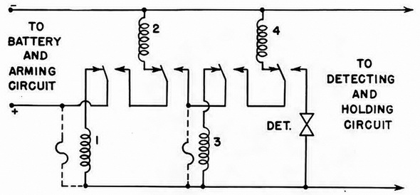
The accompanying diagram shows a typical fuse-delay switch type P.D.M. set to "3". If an actuation is registered on the unit detector, current from the battery flows through fuse-delay switch No. 1 although in some cases a by-pass fuse is used to reduce the resistance of the circuit to a value low enough to allow rapid holding in the detecting circuit. After a short delay period, switch No. 1 switches over, cutting out its own heater coil, opeing the holding circuit, and passing all current through switch No. 2 for a period long enough to allow the detecting circuit to recover. |
|
When switch No. 2 operates, it puts switch No. 3 in the circuit and the unit is alive again. As this process is repeated, switches No. 3 and No. 4 operate in a like manner, with a third actuation firing the detonator. P.D.M.'s of this type may have a many sett-ings as can be fitted to the unit's P.D.M. terminal board, with the P.D.M. setting of any unit being determined as follows: |
|
X equals 2M-2, where X equals the number of fuse-delay switches and N equals the P.D.M. setting. |
|
This device is used with BM 1000 units. |
|
Figure 297– Electrical P.D.M. (Fuse Delay Switch) Circuit |
|
|
|
|