|
|
| GERMAN UNDERWATERS ORDNANCE MINES |
| Chapter 11 - INFLUENCE MINE UNITS - SVK AND LUFTWAFFE |
| Section 6 - SUPERSONIC UNITS |
| ECHO-SOUNDER MINES TYPES AE 1 AND AE 101 |
|
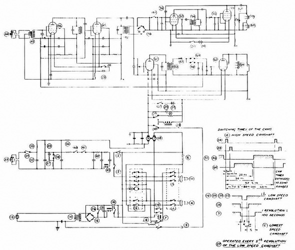
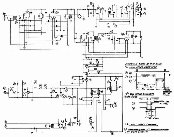
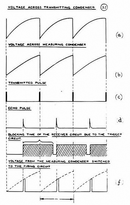
Transmitter and Firing Circuits (Figures 231, 232, 233). A pulse of current is dis-charged through the magnetostriction transmitter (33), 12.5 times per second. This is effected by contact (34), which is driven by the rotary converter and momentarily con-nects the transmitter across condenser (32) for each revolution of the high-speed cam-shaft. Between pulses, (32) is charged up to 200 volts from the rotary converter, through resistances (35) and (26). (See figure 233.) The pulse frequency is chosen to give a maximum echo range of 33 fathmos. A measuring condenser (37) is charged through resistance (39) and discharged through contact (38) in synchronism with con-denser (32). Condenser (37), however, has a long time constant of charge, so that its voltage increases almost linearly with time between each pair of discharges. (See figure 233.) When an echo is received, contacts (40) and (41) connect condenser (37) to the firing circuit; thus the volatge applied to the latter is proportional to the echo time. (See figure 233.) The firing circuit consists of a low pass filter (42) and a capacity of a low pass filter (42) and a capacity coupled relay (43). The low pass filter smoothes out the individual pulses of current from condenser (37), and hence the condenser-coupled relay (43) will not operate if the echo time remains constant. If the echo time changes, how-ever, a current passes through relay (43) which makes contact (2) and completes the detonator circuit. In order to make relay (43) operate, there must be a sudden change in echo range of at least eight to ten feet, and this change must be maintained for at least five pulses. Relay (43) is polarized so that it will only operate on decreasing echo range. |
|
The Receiver Circuit. The receiver circuit consists of three parts: |
|
1. A two-stage amplifier connected to the receiver. |
|
2. A trigger circuit connected to the amplifier output which applies a d.c. signal to the relays in the firing circuit, whose amplitude is independent of the strenght of the input signal. The trigger circuit also gives some protection against acoustic swee-pers or background noise, because it is only alive for about 10% of each echo cycle (See figure 233.) |
|
3. The AVC amplifier and an anti-sweep circuit which makes the mine momentarily passive if a signal is received at such a time in the operating cycle that an echo cannot reasonably be expected. The Germans found that without this circuit the mine fired well ahead and to the beam of E-boats, because of their large output of high-frequency sound. |
|
The Amplifier. The magnetostriction receiver (44) is connected through a tuned input transformer (45) to the two-stage amplifiier. The amplifier uses two varaible pentodes type P701 (46) and (47) with tuned anode circuits and AVC. The d-c voltage is applied to the AVC line by means of contact (48), which is closed only during the period when the echo is expected. In this way the gain of the amplifier is controlled by the loudness of the echo, and not by the directly transmitted pulse, or interfering signals. |
|
The amplifier requires an input voltage of 35 microvolts to operate the mine. |
|
The Trigger Circuit. The amplifier output is transformed by transformer (49), and the echoes are rectified into negative pulses by rectifier (50). The pulses are connected to the triggering circuit through switch (51), which is closed by the high-speed camshaft of the rotary converter only during the period when an echo is expected. This period cor-responds to an echo range of 19 to 33 fathoms in the case of the AE 1, and 5 to 22 fathoms in the case of the AE 101. |
|
The triggering circuit contains two pentodes type P700, tubes (52) and (53). The screen of tube (52) is coupled by means of transformer (54) to the anode circuit. Thus, tube (52) is made to oscillate at a frequency of about 25 kilocycles per second. This output is rectified by (55) as a negative voltage, biasing it back beyond cut-off. |
|
When an echo is received, a negative pulse from rectiifer (50) is applied to the sup-pressor grid of tube (52), which stops oscillating. Tube (52) in turn unblocks tube (53), and drives its anode more negative. This effect is made more certain by d-c feedback from the anode of (53), to the grid of (52) through condenser (56), which drives the control gird ot tube (52) more negative. Tube (52) cannot now oscillate again until the charge on condenser (56) has decayed through the grid leak of tube (52). This decay time is adjusted so that the oscillator is blocked for 90% of the time between one echo pulse and the next. (See figure 233.) |
|
The blocking and unblocking action described above causes the plate voltage of tube (53) to follow a rectangular curve. This output is differentiated by means of a small coupling condenser (57), which thus gives a positive and negative voltage peak each echo cycle, the negative peak corresponding with the echo. The positive peak is short circuited by rectifier (53), while the negative peak operates relay (59), which operates contact (41) in the firing circuit. |
|
It was found difficult to avoid relay (59) rebounding, for the whole tolerance range of supply voltage; therefore a second relay (60) was connected with its coil in series with relay's (59) coil, and its contact (40) in series with contact (41). Contact (40), however, is normally closed and its relay coil (60) is shunted with a condenser to that it opens shortly after (41) closes, and remains open during the rebound time of (41). |
|
AVC Amplifier and Anti-Sweep Circuit. The control grid of another pentode type P700, (61), is connected to the output of the two-stage amplifier by a capative potentiome-ter. The output of tube (61) is coupled to switches (48) and (64) by means of a tuned transformer (63), and a rectifier (62). Switch (48) is closed by the high-speed camshaft of the rotary convertor during the period when an echo is expected, and supplies the AVC voltage to the two-stage amplifier, as described above. |
|
Switch (64) closes after the initial noise of the transmitted pulse has dies away, and remains closed only during the period when an echo is not expected. It connects the rectified output of pentode (61) to the control grid of pentode (65). If a signal is recei-ved during the period when an echo is not expected, the control grid of pentode (65) is driven negative, thus blocking the anode circuit, across which is connected relay coil (66), which is wound on the same core as relay (60). Relay coil (66) opens contact (40), and prevents closing of the firing circuit by contact (41), thus blocking the mine, and preventing premature firing of the mine by loud continuous noise sources, such as fast ships or acoustic sweeps. |
|
|
|
|
|
|
|
|