|
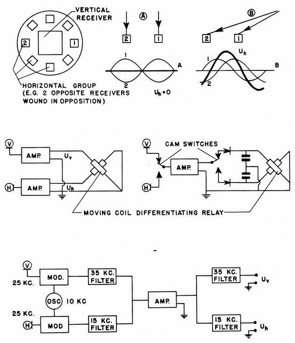
AA 4 Circuits. Several circuits were experimented with for the AA 4
unit. The first one used separate three-stage vecuum-tube amplifiers for the
vertical and horizontal direct-ional systems. The output potentials were fed
to a differentiating relay, and when the sound originated from over the mine
it fired. Some difficulties were encountered with the use of two parallel
amplifiers, since construction of two amplifiers with identical
charac-teristics proved to be difficult. The second circuit used a common
amplifier for the two systems, with a periodic switching as shown in
figure 222 to allow both systems alter-nate use of the
amplifier. The third circuit used a common amplifier, but each system was
connected to a modulator with a 10-kc. oscillator. Since the resonant
frequency of the receivers was 25 kc., the resultant beat notes were 35 kc.
and 15 kc. in each chan-nel. The vertical channel was then filtered to pass
35 kc. only, and the horizontal chan-nel filtered to pass 15 kc. only. Thus,
the two signals were fed to a common amplifier, amplified, re-filtered into
two channels, and finally sent to the differentiating relay. All three of
these circuits are shwon schematically in figure 222. |