|
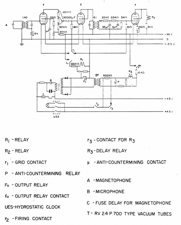
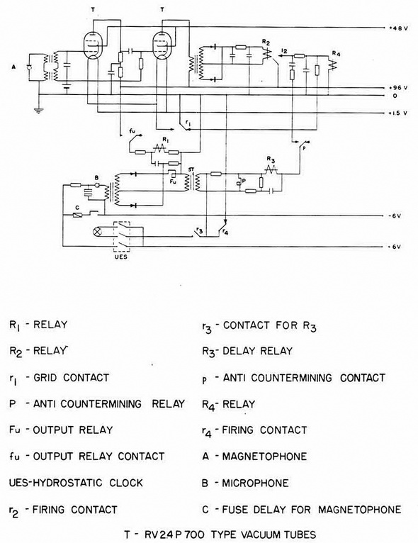
Acoustic Triggering Circuit. The modified type of acoustic
triggering circuit as used in AT 2 and AT 3 appears in their circuit
diagrams, firgures 213 and 214.
The normal can-tilever-type carbon-button microphone is used in a
transformer and rectifier circuit. The output signal current actuates relay
Fu. Closure of its conact (fu) connects relay R1 to
the 96-volt battery through a 100 K Ohm resistor. When contact (r1)
closes, it turns on the heater potential to the three tubes of the subsonic
amplifier. The resistor-condenser system in parallel with the R1
is designed to hold R1 in the operated condition for
three to four seconds if (fu) opens. This is designed to bridge any short
interruptions in the trigggering noise, but, at the same time, shut off
again if the sound is other then a con-tinuous one. This is an anti-sweep
and anti-explosion feature. A continuous sound is necessary to keep the
subsonic component of the unit alive, and it will remain alive until the
sound stops. Detonation protection is also provided by transformer ST and
its assoc-iated system. A detonation will produce a surge in the transformer
which will operate re-lay P. Closure of contact (p) connects the time-delay
system including the relay R3. When R3
is energized, contact (r3) opens, breaking the circuit
from the firing (mirco-phone) battery to the detonator. The time-delay keeps
R3 energized for a period of about three to four
seconds to allow the surge to pass. |