|
|
| GERMAN UNDERWATERS ORDNANCE MINES |
| Chapter 11 - INFLUENCE MINE UNITS - SVK AND LUFTWAFFE |
| Section 3 - ACOUSTIC MINE UNITS |
| A 105 |
|
System 3. A 7 and A 107 are modifications of A 4 and A 105, respectively. A 7 and A 107 were originally intended as plain acoustic units to be used in moored mines. How-ever, considerable difficulty with acoustic units in moored mines was encountered, due to the large background sound level. For some time the idea of using an acoustic unit in a moored mine was abandoned, since an experimental minefield of over 100 EMF mines fitted with A 3 units detonated almost simultaneously in the Kattegat. Since Dr. Hell had done most of the former work on the Navy and Luftwaffe acoustic mines, he was char-ged with the task of designing one capable of being laid in a moored mine for both ser-vices. The result was the A 7 for the Navy and his own version of A 107 for the Luft-waffe. The A 7 was still in the final testing stage at SVK at the end of the war in Europe, but the Hell A 107 for the Luftwaffe was temporarily shelved in favor of a parallel deve-lopment of Goepel of the Luftwaffe E-Stelle. Hell's system consists of either A 7 or A 105, modified by the introduction of a large condenser in the output of the rectifier circuit and remains a three-delay system. |
|
A 7 is designed for use in EMF/SMA. A 107 (Hell) is designed for use in BM 1000 T. Outside of physical differences for mounting in moored mines, A 7 is the same as A 4, with the following differences. |
|
1. In A 7 a 600/ufd condenser is inserted at the point indicated. |
|
2. In A 7, condenser C 2 is 600/ufd instead of 240/ufd. |
|
Conversion of A 105 to A 107 (Hell) is done by the same process. |
|
Goepel System. The Goepel development is quite different from the Hell system, and is essentially a two-relay system. This development had two branches: |
|
1. A 107 for moored mine BM 1000 T, and |
|
2. A 107 for ground mine BM 1000. |
|
Both systems went through several stages of development and, in each case, the system is discussed in terms of the most recent development. |
|
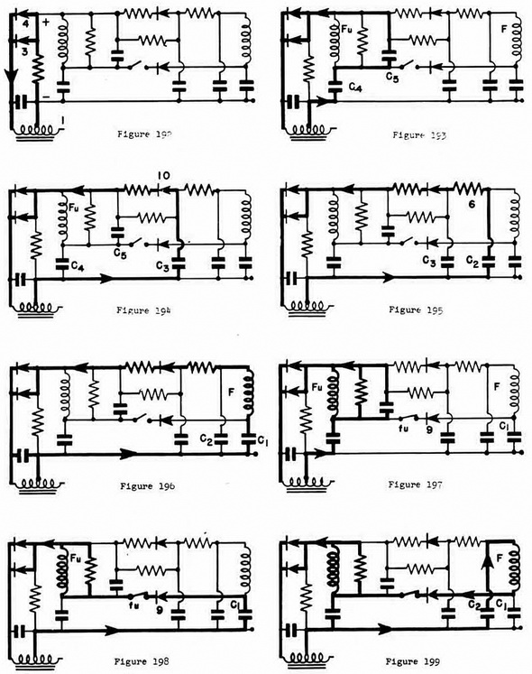
A 107 for Ground Mine BM 1000 (Goepel). In this circuit, when the master switch H closes, figure 187, the battery energizes fuze-delay switch No. 13. At the end of the de-lay on switch No. 13, it operates, producing the condition shown in figure 188 with fuse-delay switches No. 14 and No. 15 energized. At the end of the periods of No. 14 and No. 15, they operate and produce the condition shown in figure 189. The battery then fires the detonator Z. This is delay bomb firing, since the hydrostatic switch (W) has not switched over. A depth of 24 feet of water is necessary for W to operate. If sufficient depth is reached, W operates; No. 14 and No. 15 are not energized, but switch No. 16 is energized as shown in figure 190. At the end of the delay period of No. 16, it operates and opens, putting the detonator into the circuit. The carbob-button microphone (2) has been energized by the battery ever since the closure of H. Sound causes resistance variations in the microphone which are transformed by transformer (1), to the half-way rectifier circuit. As a result of the rectification produced by (3) and (4), a direct current directly proportional to the sound level appears across the terminals marked (+) and (-), as shown in figure 192. |
|
Figure 182 – A 7 Unit |
|
|
|
Figure 183 – A 7 Unit |
|
|
|
|
|
|
|
|
|
|