|
|
| GERMAN UNDERWATERS ORDNANCE MINES |
| Chapter 6 - AIRCRAFT MINES - LUFTWAFFE |
| SPECIAL ACCESSORIES UDED WITH BM 1000 |
|
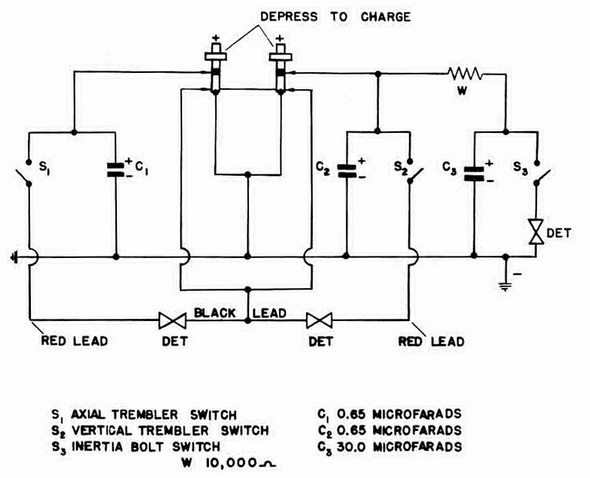
Rheinmetall Bomb Fuze - Type 157/3. While the mine is being carried by the laying air-craft, the two spring-loaded charging plungers are depressed. As the mine is released and starts to drop, a potential of 180 volts is applied to the plungers, which act as a po-sitive terminal, the fuze body being the negative terminal. When the mine clears the plane, the plungers spring up and arm the fuze firing circuit. |
|
The fuze has two functions, as follows: |
|
1. If the mine strikes a hard surface producing a deceleration of over 200g, an inertia bolt switch closes, firing the instantaneous detonator. |
|
2. If the mine strikes a surface producing a decelaration of between 20 and 200g, one or both of two vibrating "trembler" switches closes, discharging the condenser through an electric igniter in the master switch. |
|
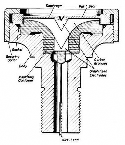
Figure 93 – Diaphragm Microphone |
|
|
|
Figure 94 – Rheinmetall Fuze Circuit |
|
|
|
Master Switch. The master switch is a positive-locking, single-pole, single-throw type, the body of which contains two spring-loaded contact plungers which bear against a contact block inside the firing device. Each of these plungers in turn is connected to an additional spring-loaded contact plunger which bears against an insulated portion of the contact bridge plunger. |
|
When the Rheinmetall fuze discharges through one or both of the switch igniters, a thermit cartridge ignites. This in turn ignites combustible material inside the switch, and the resulting heat melts a plastic plug which holds the contact bridge open. Spring tens-ion then forces the contact bridge plunger into the molten plug, thereby bridging the two side contact plungers and closing a switch in the firing circuit. A spring-loaded detent holds the contact bridge plunger in the closed position. |
|
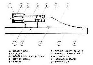
Fuse Delay Switch (Figure 96). This switch is an electrically-operated delay type used in conjunction with delay bomb firing and period delay mechanism operation in this mine. It consists of a small cylindrical shell, D, mounted in a fuze clip, L, on an insulating board, I. A circuit is made from H to K through the spring copper strip, G, down the spring-loaded spindle, F, which is held in place by the adhesive action of a soft solder plug, B. The circuit continues from the spindle into the heater coil, A, and out through the shell, D. At the end of a heating period predetermined by the basic switch design, the solder melts and spring, E, forces spindle, F, to the left, thus breaking the circuit from H to K and making a circuit from H to J through the conducting strip, G. |
|
Figure 96 – Fuse Delay Switch |
|
|
|
|