|
|
| GERMAN UNDERWATERS ORDNANCE MINES |
| Chapter 4 - CONTACT AND MOORED INFLUENCE MINES |
| BASE PLATES |
|
All German moored contact mines are spherical or have cases consisting of two hemis-pherical joined by a cylindrical mid-section. The cases are of mild steel, vary in diameter from 26 inches to 46 inches, and are loaded either with cast or block-fitted Hexanite. Chemical and switch horns are employed, either singly or in combination. |
|
Mines of this type usually derend on mooring tension for arming and disarming, these processes being controlled through the mooring spindle on the base plate. General cha-racteristics are given below: |
|
All base plates are fitted with straight-shank mooring spindles which are withdrawn by mooring tension against tension of a coil spring mounted on the inside of the base plate. |
|
Withdrawal of the mooring spindle performs the following functions: |
|
It trips the booster release lever. |
|
It arms the self destroying mechanism. |
|
It closes the mooring safety switch. |
|
The booster release lever is mounted in the booster tube and is connected, by means of a mechanical linkage to the mooring spindle. The lever holds the booster in the "Safe" position above the detonator until the mooring spindle is withdrawn, at which time the lever is tripped and the booster is freed to drop over the detonator. |
|
The self-destroying mechanism may be either an electromechanical internal horn (oft-en referred to as the "eight horn") used in the Type EMC II base plate, or a rotary, two-position switch used in the Type EMC I or UMA base plate. |
|
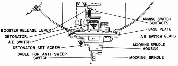
Figure 41 – Base Plate Type EMC II (Exterior) |
|
|
|
Figure 42 – Base Plate Type UMA (Exterior) |
|
|
|
The horn-type self-destroying mechanism is mounted in a casting secured to the in-side of the base plate by four bolts. Its operation is controlled by a mechanical linkage connected to the mooring spindle. Withdrawal of the spindle allows a cocking pin to move the armed position, and retraction of the spindle pivots the cocking pin and releases a spring-loaded firing pin, which shatters the electrolyte ampoule. The electrolyte then runs into a battery, energizing it, producing a momentary current sufficient to fire the detonator and main charge, if the self-destroying mechanism its in the firing circuit. |
|
The switch-type self-destroying mechanism is mounted on a bracket on the inner end of the mooring spindle and is connected to the base plate by a mechanical linkage. With-drawal of the spindle carries a small pin into position behind a can. Retraction of the spindle carries the cam back with the pin and closes the switch. |
|
The various base plates use the following type of mooring safety switches: |
|
With Base Plate Type EMC – a switch consisting of four contacts, two of which are mounted on the mooring spindle and two on the mooring spindle housing. Withdrawal of the spindle makes the contacts, arming the horn circuit. Retraction of the spindle breaks the contacts, disarming the horn circuit. |
|
With Base Plates Types EMC I and UMA - a two position rotary switch mounted on a bracket on the mooring spindle and connected to the base plate by a mechanical linkage. Withdrawal of the mooring spindle closes the switch, arming the horn circuit. Retraction of the spindle opens the switch, disarming the horn circuit. |
|
With Base Plate Type EMC II - a switch consisting of two main parts: a cylindrical, bakelite housing mounted on the base plate and enclosing the inner end of the mooring spindle; two bakelite-covered brass cylinders mounted one above the other on the inner end of the mooring spindle. The latter are fitted with brass contact pieces, and the for-mer with spring-loaded contacts. Withdrawal of the spindle pulls down the two cylinders with respect to the housing, so that the contact pieces make their respective contacts, arming the horn and self-destroying mechanism circuits. Retraction of the spindle breaks the upper set of contacts, disarming the horn circuit. The lower set is in the SDM circuit and remains closed, being locked by a spring-loaded detent. |
|
With Base Plate Type UMB - a switch consisiting of eight contacts, four of which are mounted on a cross-head on the mooring spindle and four on the mooring-spindle hous-ing. Withdrawal of the spindle makes the contacts, arimg the horn circuit. Retraction of the spindle breaks the contacts, disarming the horn circuit. However, the mooring spindle is designed to lock in the "out" position. |
|
Figure 43 – Base Plate Type UMB (Exterior) |
|
|
|
A detonator carrier is fitted in a well located externally on the base plate beside the mooring spindle, and is held in place by a strongback and a single setscrew. The screw fits into a boss on the detonator carrier and is secured by a U-pin which fits into an an-nular groove on the setscrew. Two spring-loaded contacts are mounted on the inside of the base plate, extending vertically upward and then bending at an angle of 90° to enter the booster tube. These contacts make similar contacts on the detonator carrier when it is inserted in the booster tube. |
|
A spindle which controls an internal, two-position rotary switch is mounted at either 90° or 135° from the detonator carrier. A red arrow is stamped on its face to indicate the switch setting and the letters A and E are stamped on the part of the base plate adjoining. This switch is in the circuit of the SMB, except in base plate Type UMB, where it is in the circuit of the UMB, where it is in the circuit of the "tombac" anti-sweep devi-ce. If the arrow points to A (painted white), the switch is open and the self-destroying mechanism or "tombac" is not in the cirucit. It the arrow points to E (painted red), the SDM or "tombac" is in the circuit and both should operate as designed. |
|
A soluble plug holder may be found alongside the mooring spindle, secured by a strongback. A black, plastic disc, about a half inch in diameter, is fitted in the strong-back. Withdrawal of the mooring spindle upon dissolution of the soluble plug pushes this disc out of the strongback. Note that the presence or absence of this disc provides a positive means of determining whether or not the mine has ever armed. |
|
In same cases, the following additional base plate fittings may be found: |
|
A gland for connecting a lower antenna or "tombac" anti-sweep device. |
|
A slotted screw plug for applying a circuit tester. |
|
Figure 44 – Base Plate Type EMC II (Interior) |
|
|
|
Figure 45 – Base Plate Type UMA (Interior) |
|
|
|
Figure 46 – Base Plate Type UMB (Interior) |
|
|
|
Figure 47 – Eight Horn |
|
|
|
Figure 48a – Diagram of Base Plate Type EMC II |
|
|
|
Figure 48b – Diagram of Base Plate Type UMA |
|
|
|
Figure 48c – Diagram of Base Plate Type UMB |
|
|
|
|