|
|
| GERMAN UNDERWATERS ORDNANCE MINES |
| Chapter 4 - CONTACT AND MOORED INFLUENCE MINES |
| THE GERMAN EM (EINHEITSMINE) MINE SERIES |
|
The EMF Mine. The EMF was the first moored influence mine developed by the Ger-mans. Its design was undertaken in 1928 and completed in 1931. In 1936 the base plate was revised and the mine put into production. By 1939 it was ready for operational use, but the magnetic unit in existence proved unsatisfactory. In 1941 the M 3 had been per-fected and adapted for wuse with the EMF. At about the same time unsuccessful at-tempts were made to fit this mine with an acoustic unit known as A 3. The mine was laid operationally only with the M 3 unit. It was contemplated that the following influence unit should be fitted to the mine: |
|
1. M 4 |
|
2. AA 4 (Unit abandoned in 1944) |
|
3. A 7 |
|
4. AE 1 |
|
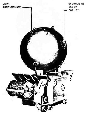
The EMF used the EMC anchor and was designed for surface laying only (Figure 18). Its larger counterparts, the SMA, SMB, and SMC were, on the other hand, designed for sub-marine laying only. |
|
The first model was a spherical case consisting of two hemispheres welded together. Its flooder plate was located 26½ inches from the center of the upper hemisphere; how-ever, there were no provisions for an 80-day clock. In the final model the case was im-proved in construction; a soluble plug and disarming switch were added; and the depth taking mechanism was improved. |
|
Description of case. |
|
Shape |
Two hemispheres, joined by a cylindrical mid-section |
|
Diameter |
45 in. |
|
Length |
50 in. |
|
Charge |
750 lb. block-fitted hexanite |
|
Description of External Fittings |
|
Horns |
Two 60° apart on upper hemisphere, 20½ in. from center |
|
Anchor-securing lugs |
Three, hock shaped; two on lower hemisphere, 160° apart, 11½ in. from center; one on upper hemisphere, 28½ in. from center |
|
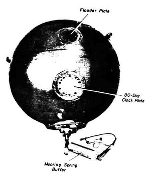
Flooder plate |
6-in. diameter, on upper hemisphere, 28½ in. from center, secured by 10 bolts |
|
80-day clock cover plate |
8-in. diameter, in lower hemisphere, in line with flooder plate, 23½ in. from center, secured by 10 bolts |
|
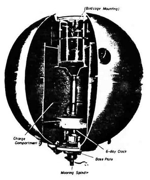
Operation. The mine takes depth by plummet. Mooring tension pulls out the mooring spindle, tripping the booster release lever and releasing the locking balls from the clock-work spindle. Water pressure depresses the clock spindle at a depth of 15 feet, starting the clock. The clock runs off ist delay period, and the unit starts its testing cycle. If the mine does not orient itself properly after a pre-set time of up to 12 hours, a scuttling charge will fire to sink the mine. |
|
The only self-disarming device is the 80-day clock, which is designed to scuttle the mine if the clock stors at any time prior to completion of its set period or upon complet-ion of its set period. |
|
The operational characteristics of this mine are as follows: |
|
Laying heights and speeds |
13 ft. – 25 knots 16 ft. – 18 knots |
|
Laying depths |
325 ft. – with cable ½ in. 650 ft. – with cable 7/16 in. 985 ft. – with cable 3/8 in. 1640 ft. – with cable 5/16 in. |
|
Minimum laying depths |
130 ft. (80 + 50) |
|
Minimum and maximum case depths |
50 to 115 ft. |
|
In 1944 experiments were conducted with an EMF case made of a plastic material called "Eternit". This model was known as EMF (Et) and consisted of two Eternit hemis-pheres bolted together to form a sphere similar in dimensions and fittings to the normal EMF. It was undergoing tests at the close of the war. |
|
Figure 18 – EMF II Mine |
|
|
|
Figure 19 – EMF Mine |
|
|
|
Figure 20 – EMF Mine with M 3 Unit |
|
|
|
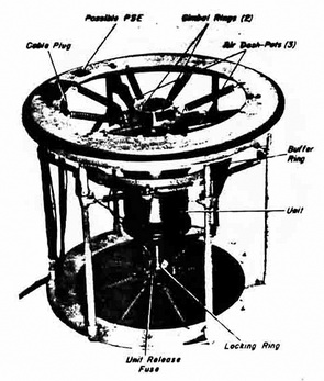
Figure 21 – EMF Mine - Birdcage Suspension for M 3 Unit |
|
|
|
|