|
|
| GERMAN UNDERWATERS ORDNANCE MINES |
| Chapter 4 - CONTACT AND MOORED INFLUENCE MINES |
| THE GERMAN EM (EINHEITSMINE) MINE SERIES |
|
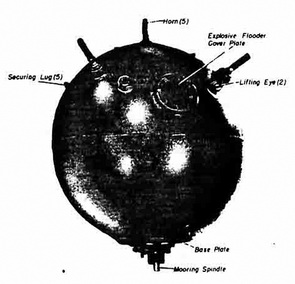
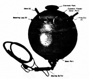
The EMD Mine. The first EMD mine was ready for operational use in 1924. It was a moored contact type fitted for five chemical horns, and was designed for use against surface craft only; consequently, it had no lower horns. Except for the absence of such horns and its smaller size, the EMD is practically identical to the EMC. (Both mine types use the same base plates, anchors, and accessories). In 1936 it was improved along the same lines as the EMC, the new model being designated EMD II and the original type EMD I. A small cover plate, 6.5 inches in diameter, equidistant from the lifting eyes and 25 inches from the center of the upper hemisphere, was added to accommodate an 80-day clock and flooder. Later, an electrode plate mounted on a plastic cover and placed in the center of the upper hemisphere was added as an antenna connector. |
|
The manufacture of EMD II was discontinued in the early part of World War II to per-mit greater production of the EMC II, which was considered more suitable. Existing stocks of EMD I and EMD II were laid operationally. |
|
General |
|
Moored, contact, chemical-horn mine, laid by surface craft. |
|
Offensive or defensive mine, for use in maximum depth of water of 1100 feet. |
|
Description of Case |
|
Shape |
Spherical |
|
Material |
Steel |
|
Diameter |
40 in. |
|
Charge |
330 lb. block fitted hexanite |
|
Description of External Fittings |
|
Horns |
Five: one in center of cover plate; four equally spaced around upper hemisphere, 20-in. from center |
|
Cover plate |
7.5-in. diameter, in center of upper hemisphere flush type, secured by 10 bolts |
|
Base plate |
Standard Type EMC II |
|
Lifting eyes |
Two, 16.5 in. apart, 22.5 in from center of upper hemis-phere |
|
Securing lugs |
Five: one 22.5 in. from center of upper hemisphere; one 31 in. from center of lower hemisphere; three, staggered, 12 in. from center of lower hemisphere |
|
Operation. Mine take depth by plummet. Mooring tension pulls out the mooring spindle, which closes the mooring safety switch, trips the booster release lever, and arms the mine. |
|
Standard chemical-horn firing. |
|
The only self-disarming device is the mooring safety switch which is designed to dis-arm the mine by opening the firing circuit upon release of mooring tension. |
|
Figure 14 – EMD I Mine |
|
|
|
Figure 15 – EMD II Mine - Upper-Lower Antenna |
|
|
|
Figure 16 – EMD II Mine- Cross Section |
|
|
|
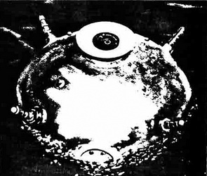
Figure 17 – EMD II Mine Afloat |
|
|
|
|