|
|
| BRITISH EXPLOSIVE ORDNANCE |
| Part 7 - Chapter 2 |
| Firing Devices |
|
Pull-Pressure-Release Switch No. 13 (Service) |
| Data |
|
Width |
½ in. |
|
Height |
1 in. (without adjuster) |
|
Length |
23/16 in. (without fuse adapter) |
|
Total weight |
3 oz. |
|
Material |
Mazak |
|
Color |
Black |
|
Operating load |
Pull, 3 lb.; pressure, 35 - 50 lb.; release 2 lb. |
|
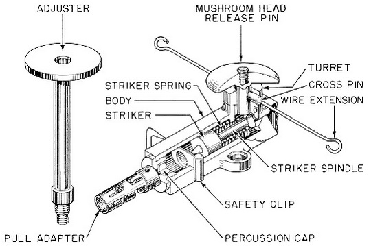
Description: The square body of this switch is made of die-cast Mazak, and has two perforated lugs at the center to facilitate placement. The body is drilled longitudinally, and internally threaded at one end to take a fuse adapter, which carries a 1.7 grain "B" composition detonator. |
|
The spring-loaded striker and striker spring fit into the body. The striker has a large head to carry the striker point, a slender middle stem, and a beveled flange on its after end. |
|
The body carries a boss on its top face near the after end. A small rotable turret is secured in the boss by a wire staple, and is centrally drilled to receive a steel release pin, which terminates in a mushroom head. |
|
The turret and release pin are cross drilled for insertion of a cross pin, which prevents vertical movement of the release pin, but still allows it to rotate with the turret. The cross pin is secured to a short length of piano wire, witch passes through its center and is looped at both ends. The top face of the turret has narrow vertical slots leading to the cross-drilled holes, so that the extension wire can escape vertically when the cross pin has been withdrawn sufficiently. These slots are not wide enough to allow the es-cape of the cross pin itself. When the release pin is in place and the cross pin has been inserted, the lower end of the release pin engages the beveled flange on the after end of the striker to hold the cocked striker in position. |
|
A slot through the body enables a flat safety clip to be inserted between the striker and the detonator. A central hole in the clip engages the striker point, if the striker is re-leased while the clip is in place, and prevents withdrawal of the safety clip, as well as any further forward motion of the striker. |
|
The mushroom head of the release pin is centrally threaded to take an adjuster. This adjuster is a rod having a flat head at one end and two sets of threads at the opposite end. The first set of threads screws into the release pin, while the second set carries a knurled locking nut which enables the height of the flat head to be adjusted between 3¼ in. and 4¾ in. above the base of the switch. |
|
This device may be used in booby-trap installations where pull-pressure, or release-of-pressure operation is desired. It may also be used to initiate demolition charges. Its adjustable head and release or pressure firing make it suitable for use beneath railroad tracks, crates, etc. The device is unaffected by water and will function when immersed. |
|
Installing and Functioning: |
|
Pull-Operation – The switch is fastened in place and the charge connected. The fuse adapter will take either a Detonator No. 27 or a fuse. The cross pin must be in place for pull operation. Trip wires can be run from either end of the cross pin in any direction, lim-ited to a single plane perpendicular to the vertical axis of the release pin. The device can also be arranged to operate on release of tension by slight improvisation. The safety clip must be removed after setting. If the safety clip can not be easily withdrawn, the device must be either recocked or discarded and replaced by a new device if faulty. |
|
A pull on the trip wire of approximately three pounds will retract the cross pin suffici-ently so that the extension wire is free to move up the vertical slots in the turret head, thus leaving the release pin free to move upward. The beveled flange on the striker, which is forced against the bottom of the release pin by the compressed striker spring, cams the release pin upward, thus freeing the striker. The striker fires the detonator. |
|
Pressure Operation – The switch is secured in place, the charge connected, and the safety clip removed. The cross pin must be in place for pressure operation. The adjuster may be used in placing the switch. |
|
When the mushroom head of the release pin or the adjuster plate is subjected to a load of 35 to 50 lb., the striker stem is fractured by the bottom end of the release pin, freeing the spring-loaded striker, which is forced forward to fire the detonator. |
|
Relase Operation – The switch is secured in position, the charge connected, the cross pin removed, and the safety pin is removed. The adjuster may be used in placing the switch. A load of two pounds on the adjuster plate or release-pin head will maintain the switch in the cocked position. |
|
When the restraining weight is removed, the beveled flange on the striker, which is forced against the bottom of the relase pin by the compressed striker spring, cams the release pin upward, thus freeing the striker. The striker fires the detonator. |
|
A switch set for release operation may also be fired by pressure if sufficient weight is applied. |
|
Disarming: If the fuse is set for pull operation, check both ends of the trip wire, cut the trip wire, and insert a safety clip in the switch. Disconnect the charge, and remove the fuse adapter. When checking the trip wire, ascertain that the switch has not been arranged to operate by release of tension. |
|
If the fuse is set for pressure operation, insert the safety clip, and remove the switch after making sure that the cross pin is properly in place. Disconnect the charge and re-move the detonator. |
|
If the switch is set for release operation, insert a safety clip in place, insert a wire or nail large enough to fill the hole into the cross pin holes, and remove the switch. Discon-nect the charge and remove the detonator. |
|
If the switch is not readily accessible, it may be necessary to cut the fuse leading to the charge, or to destroy the switch in place. |
|
|
| Figure 279 – Pull-Pressure-Release Switch No. 13 Mk I |
|
|