|
|
| BRITISH EXPLOSIVE ORDNANCE |
| Part 7 - Chapter 2 |
| Firing Devices |
|
A./P. Switch No. 8 Mk I (Service) |
| Data |
|
Diameter |
Body, ½ in.; top plate 1½ in. |
|
Length |
5¾ in. |
|
Total weight |
4 oz. |
|
Material |
Steel |
|
Pressure required |
10 lb. (approx.) |
|
Color |
Black, olive drab, or unpainted steel |
|
Explosive |
.303 cartridge |
|
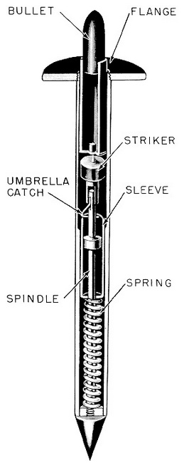
Description: The switch consists of a hollow metal spike, flanged at the open end, which can be pressed into the ground or hammered with care into a road. Inside the spike is placed the firing assembly, consisting of a metal spindle, flanged at the base with an umbrella catch located near the top. A spring and spring retaining sleeve fit over the spindle and are held compressed by the umbrella catch. Over the top of the spindle is placed a striker with a hollow shaft, and on top of this is placed a rimless .303 cartridge, with a bullet which just protrudes out of the spike. |
|
Functioning: Slight pressure on top of the bullet forces the hollow shaft of the striker over the umbralla catch, releasing the sleeve which holds the spring in compression. The spring drives the sleeve upward against the striker head, forcing the striker into the base of the cartridge and firing the cartridge. |
|
Use: This self-contained unit, which discharges a bullet, is sunk into orads and path-ways. Fired by pressure, the bullet will perforate a man's foot or severely damage a pneumatic tire. |
|
Installing: This assembly usually is issued cocked and ready for use, being held in position in the spike by a cork. If it is necessary to cock the switch, first push the empty barrel into the ground to the level of the flange. Place the spring-retaining sleeve, roun-ded end down, over the spring, and push down until the catch engages over the top of the sleeve. Place the cocked mechanism in the barrel of the switch, and lower the striker into the barrel. At arm's length, lower the cartridge gently into the barrel with the point upward. Hold the cartridge between the fingers when inserting to minimize the danger in case of premature firing. |
|
Disarming: Carefully remove the cartridge from the pistol by grasping it between the fingers at arm's length. |
|
Remarks: Test this switch by cocking the mechanism and inserting the striker. De-pressing the striker with the blunt end of a pencil will compress the catch and release the spring-retaining sleeve. The impact can be felt in the pencil. Never use the cartridge for testing. |
|
Never place the cartridge in the spike except when laid. |
|
|
| Figure 274 – A./P. Switch No. 8 Mk I |
|
|