|
|
| BRITISH EXPLOSIVE ORDNANCE |
| Part 7 - Chapter 2 |
| Firing Devices |
|
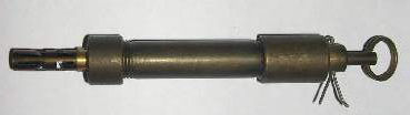
Pull Switch No. 1 Mk I (Service) |
| Data |
|
Diameter |
5/8 in. |
|
Length |
4 in. (with fuse adapter) |
|
Weight |
2¾ oz. |
|
Material |
Steel |
|
Pull required |
2 lb. |
|
Color |
Olive drab |
|
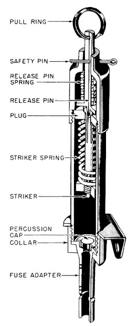
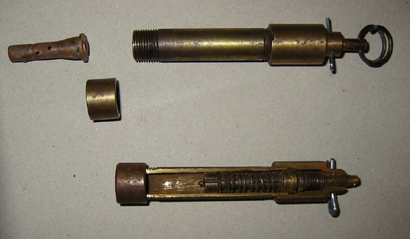
Description: This switch consists of a housing tube containing a release pin and spring, a plug, a spli-headed striker, and a striker spring. In the cocked position, the split head of the striker is spread over the top of the plug by the insertion of the nib on the end of the release pin. The striker is thus held under spring compression. A safety pin is inserted through the housing tube and the release pin, preventing the latter from being disengaged from the split head of the striker. |
|
An anchor bracket is slipped over the housing tube to enable the switch to be ancho-red in any convenient position, and a screwed collar is threaded over the open end of the tube for attachment of the cap holder. |
|
Functioning: A pul on the trip wire attached to the pull ring removes the release pin from the split head of the striker, which contracts sufficiently to pass through the open-ing in the plug. The striker spring the drives the striker into the percussion cap. |
|
Use: This is a pull-type firing device used to initiate either booby-trap installations or demolition charges. It is designed to operate when a direct pull is exerted on a trip wire attached to the release pin. If fires a percussion cap in a holder which can be connected either to instantaneous fuse or a Detonator No. 8. |
|
Installing: Remove the fuse adapter by unscrewing the collar. Anchor the switch by means of the bracket. Replace the collar without the fuse adapter. Install a loose trip wire, and connect the charge to the fuse adapter with detonating cord. Replace the fuse adapter on the switch by means of the collar. Withdraw the safety pin gently. With pro-per installation, the safety pin should be loose in the safety-pin hole. |
|
Disarming: Insert the safety pin in the safety-pin hole. Cut the trip wire, and remove the fuse adapter. |
|
Remarks: To re-use this switch, make the following test. Unscrew the collar, and re-move the fuse adapter. Hold the switch with its open end against a piece of wood. Re-move the safety pin and gently pull the release pin. The striker should descend its point well into the wood. To recock, push back the striker with a pencil or other wooden rod until the release pin slips into the split head of the striker and locks it in place. Reinsert the safety pin. |
|
To enable this switch to be used for electric firing when desired, a special electric adapter is supplied. This consists of a small unit made of insulating material and fitted with two contact points, from which are led two lengths of rubber-insulated flexible wire. The contact points are enclosed by a copper cap which is spun in position on the insula-ting body, and cannot be removed. The unit replaces the percussion cap in its holder. When the striker operates, instead of piercing the percussion cap, it drives down the center portion of the copper cap so that the two enclosed contacts are short-circuited. Visual inspection will indicate whether the copper cap has suffered accidental damage. If it is dented at all, the adapter should be discarded. |
|
To fit an electric adapter, removes the collar from the end of the switch. Remove the percussion-cap holder and insert the copper-capped end of the unit inside the tube. The collar may now be threaded on over the wire leads and replaced. The adapter must be wired in series with a battery and an electric detonator. Final connection should not be made until the switch has been installed. |
|
|
| Figure 267 – Pull Switch No. 1 Mk I |
|
|
|
|
|
|