|
|
| BRITISH EXPLOSIVE ORDNANCE |
| Part 5 - Chapter 2 |
| Anti-Personnel Grenades |
|
A./T. Hand Grenade No. 75 Mks I, II, and III (Service) |
| Data |
|
Over-all length |
6½ in. |
|
Width |
3 5/8 in. |
|
Height |
1 7/8 in. |
|
Total weight |
2¼ lb. |
|
Filling |
Nobel's No. 704 B, Ammonal, Burrowite, or TNT (all with ex-ploder or C.E. pellets) |
|
Filling weight |
1¾ lb. |
|
Fuzing |
Mk I, Grenade Igniter No. 75 Mk II; Mk II and III, Detonator No. 83 |
|
Delay |
None |
|
Color |
Buff |
|
Markings |
Cap painted pink when Burrowite or Ammonal filled; red filling ring below cap indicates Victor Powder or Exp. No. 673 exploder; ring of red crosses indicates Polor Dynamite exploders |
|
Pressure to fire |
300 lb. |
|
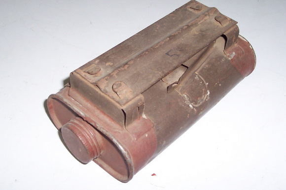
Description: The Grenade Mk I consists of a 1-pint capacity, flat, tin-plate can, which is rectangular in shape, and has rounded corners. It is filled through a hole in the end, over which a tin cap is screwed and cemented to provide watertightness. On one side of the can are two metal pockets with slots cut in them, which form the detonator holders. These pockets have malleable metal tabs which are bent to close them. The striker plate is supported above the detonator holders by two brackets, one on each end of the can. The striker plate is a light metal plate with a transverse projection on the bottom which serves as a striker. It is secured to the brackets by two bent tabs, so that the striker is immediately over the slots in the detonator holders. The principal differen-ces between the Grenade Mk I and Mk II lie in the fuze pockets, which in the Mk II are set at an angle for easier insertion of the fuze assemblies, and in the detonator assemb-lies. The Grenade Mk III is similar to the Mk II, but has no filling cap. It is filled with 1¾-lb. TNT, and two C.E. pellets. |
|
The fuze for the Grenade No. 75 Mk I consists of an Igniter No. 75 Mk II and a deto-nator. Two of these units are used with each grenade. The igniter is a tin-plate tube closed at one end by flattening, and it is painted red. It contains an acid-filled glass am-poule, and ignition composition. A rubber tube is rolled onto the igniter. The detonator is an aluminum tube open at one end, and is smaller in diameter than the igniter. The deto-nator is slipped into the open end of the igniter, and the rubber tube rolled over the joint to provide waterproofing. |
|
In the Grenades Mk II and Mk III, the detonator unit are manufactured and issued in one piece. Each Detonator No. 83 consists of a bakelite holder containing a glass ampou-le, the end of which is sealed with wax. A striker pin is held in the top of the holder by means of a red cellulose seal. The detonator fits tightly over a tubular projection on the holder, and is sealed on with glue. As with the Grenade Mk I, two assemblies are provi-ded with each mine. Pressure on the plate forces the striker pins into the ampoules, which fire the detonators and thus the main charge. The Grenade Mk II uses the C.E. fil-led Detonator No. 83 Mk I, while the Mk III grenade uses the RDK filled Detonator No. 83 Mk II, which is also designated No. 96 Mk I. |
|
The grenade is so shaped that when thrown it will come to rest with the striker plate either on top or underneath. It will operate equally well in either position. |
|
Operation: For the Grenade No. 75 Mk I, insert the open end of the detonator into the open end of the igniter. Then roll the rubber tube on the igniter to cover the joint. This provides a water-tight seal. Insert a detonator assembly, detonator end first, into each of the pockets of the detonator holder through the hole in the striker-plate brack-et. Bend over the metal tabs, thus securing the detonator assembleis in the pockets. The red painted portions of the assemblies should now be visible in the slots of the deto-nator holders. The grenade is thrown or placed so that it will be run over. The pressure of the vehicle upon the striker plate will force the strikers through the slots in the deto-nator holders, crush the igniter tubes, and break the glass ampoule containing nitric and sulphuric acid. The action of the acid on the potassium chlorate and charcoal ignition composition produces an immediate flash, which sets off the detonators and explodes the grenade. |
|
In the Grenade No. 75 Mk II and Mk III, the igniters are inserted in their pockets and the tabs bent into place to secure them. When the grenade is run over, the striker pin crushes the glass ampoule and grinds the broken glass and contained igniter composition together, igniting the composition. The resultant flash initiates the detonator, which ex-plodes the grenade. |
|
Remarks: When the Grenade No. 75 is filled with Ammonal, the designation is chang-ed to No. 75 A. Ammonal is about 80% as powerful as the regular fillings. |
|
The Grenade No. 75 is actually employed mainly as a land mine for defense against ar-mored cars, tanks, and other vehicles. It will disable light tanks and vehicles and is used principally for hasty minefields. |
|
The Grenade No. 75 is often referred to as the "Hawkins" grenade. |
|
|
| Figure 239 – A./T. Hand Grenade No. 75 Mk I |
|
|
|
|
Figure 240 – No. 75 |
Figure 241 – Detonator No. 83 |
|
|
| Figure 242 – A./T. Hand Grenade No. 75 Mk II |
|
|
|
|