|
|
| BRITISH EXPLOSIVE ORDNANCE |
| Part 5 - Chapter 2 |
| Anti-Personnel Grenades |
|
A./T. Rifle Grenade No. 68 Mks I - VI (Obsolete) |
| Data |
|
Over-all length |
7 in. |
|
Diameter |
2.5 in. |
|
Total weight |
1 lb. 15½ oz. |
|
Filling |
RDX/BWX 91/9, P.S., Lyddite, C.E./TNT 30/70 or Pentolite |
|
Filling weight |
5.5 oz. |
|
Delay |
None |
|
Color |
Buff |
|
Markings |
Red filling band around top and green band around center of body |
|
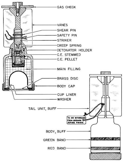
Description: The grenade consists of a steel or Mazak bell-shaped body fitted with a tail. The open end of the body is fitted with a thin metal cavity liner, which forms a hol-low in the H.E. fitting. The cup is secured by a screw collar. The dome of the body is bo-red to carry the detonator holder and threaded to receive the tail section. The tail has four straight vanes and is centrally recessed to receive the striker. A copper shear wire and safety pin secure the striker in position. The pin is removed before the grenade is fi-red. The gas check plates are secured either by metal rivets, or in an integral casting with the fins of the grenade. |
|
The following differences exist among the various marks of the grenade. The Grenade Mk I has small tail vanes and an additional small set of vanes on the body. A steel gas check is secured to the tail by a bakelite or brass screw. The brass cavity liner is hemis-pherical in shape. |
|
In the Grenade Mk II the small vanes were removed from the body and the tail vane enlarged. The gas check was secured by a brass screw or by crimping the tail. In the Mk III a cylindro-conoidal steel cavity liner was substituted for the hemispherical liner previously used. The gas check was either secured by crimping, or was made of Mazak cast integrally with the tail unit. The Grenade Mk IV employed a new type of detonator holder, and had the tail unit and gas check cast integrally of Mazak. The Grenade Mk V also employed the new detonator holder, but used the steel gas check secured by crimp-ing. |
|
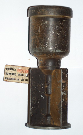
The Mk VI was produced in the United States. The tail unit consisted of a steel tail tube to which the tail fins were spot welded. A wooden plug, secured by a shoe rivet, closed the after end of the tail tube. |
|
Operation: Before the grenade is fired from the discharger, the safety pin must, be removed. The striker is located slightly away from the rear of the tube containing it. On steback, the striker moves to the rear, shearing the shear wire. It is then held only by the creep spring. On impact, the striker overcomes the creep spring and hits the detona-tor to explode the grenade. The effective range is given as 50 to 75 yards. |
|
|
| Figure 236 – A./P. Rifle Grenade No. 68 Mk II |
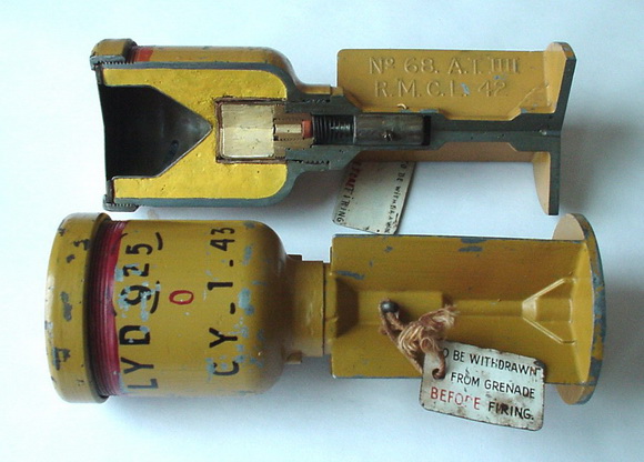 |
| A./T. Rifle Grenade No. 68 Mk III |
|
|
|
|
A./T. Rifle Grenade No. 68 Mk IV |
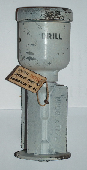
A./T. Rifle Grenade – Drill |
|
|