|
|
| BRITISH EXPLOSIVE ORDNANCE |
| Part 4 - Chapter 2 |
| Rocket Nose Fuzes |
|
Nose Fuze No. 725 Mk I (Service) |
| Data |
|
Rockets used in |
Shell, H.E., 3-in., 29-lb. Mk I |
|
Action |
Instantaneous on impact |
|
Armed condition |
No external evidence |
|
Body diameter |
2.4 in. |
|
Over-all length |
5.75 in. |
|
Color |
Nose cap, brass; body, aluminum; shipping cap, black |
|
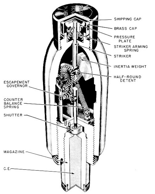
Description: This fuze consists of an aluminum alloy fuze body with an ogival external contour. A thin brass cup is crimped over the forward end of the fuze body, which also is threaded to receive a black metal shipping cap. A C.E. booster is housed in a magazine, which threads into the base of the fuze. |
|
A centrally located striker extends the full length of the fuze. A mushroom-shaped pressure plate is fixed to the top of the striker by a split pin. The lower end of the striker terminates in an integral firing pin, which extends into a blind hole in the detonator shut-ter, retaining the detonator in the offset position when the fuze is unarmed. A compres-sed spring separates the pressure plate from the forward end of the fuze body and tends to force the striker and plate upwards. This upward motion of the striker is prevented until after firing by a half-round rotary detent, which engages a slot cut in the striker spindle. |
|
Rotation of the half-round detent is accomplished by an escapement-controlled arm-ing mechanism. This mechanism is powered on setback by the rearward movement of a pivoted inertia block. Motion of the block causes the attached gear train to rotate the detent. Speed of arming is controlled through the escapement mechanism. |
|
Operation: Partial arming results during the setback or acceleration stage. The iner-tia block moves through an angle of about 60°, initiating the gear train, and rotating the detent through about 135°. When the inertia block has reached its aftermost position, the flat face of the detent is presented to the slot in the striker. The striker is now free to move upwards under force of the arming spring and free the detonator shutter, as soon as acceleration of the round ceases. When deceleration begins, the striker is moved upwards, the detonator aligned beneath the striker, and the fuze is fully armed. |
|
The thin brass nose cap is crushed on impact, and the pressure plate and striker are forced down into the detonator, initiating the explosive train. |
|
Remarks: This fuze was designed to replace the No. 721 Mk II* and III, when used in the "Land Mattress", but its use may be extended to include the 5-in. (H.E. Shell) "Sea Mattress", and the 60-lb. F. Shell, No. 1 Mk I for the 3-in. Aircraft Rocket. |
|
|
| Figure 226 – Nose Fuze No. 725 Mk I |
|
|