|
|
| BRITISH EXPLOSIVE ORDNANCE |
| Part 3 - Chapter 3 |
| Rocket Flares |
|
2-in. U.P. Target Rocket (Service) |
| Data |
| Target Head | ||
|
Over-all length |
15.75 in. | |
|
Diameter |
2.25 in. | |
|
Total weight |
4.5 lb. | |
|
Fuzing |
Special Igniter |
|
| Rocket Motor | ||
|
Over-all length |
20.25 in. | |
|
Diameter |
2.25 in. | |
|
Width of fins |
2.375 in. | |
|
Total weight |
6.0 lb. | |
|
Propellant |
Cogged cordite | |
|
Propellant weight |
1.25 lb. | |
|
Burning time at 60° F. |
0.45 sec. |
|
|
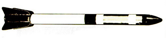
General: This rocket is designed to give, by means of an integral flare, a visible aim-ing mark for antiaircraft batteries. The target has a range of about 5,000 yards at a speed of 250 to 400 knots. The target can be used at night and is suitable for use from either aboard ship or ashore. |
|
Description |
|
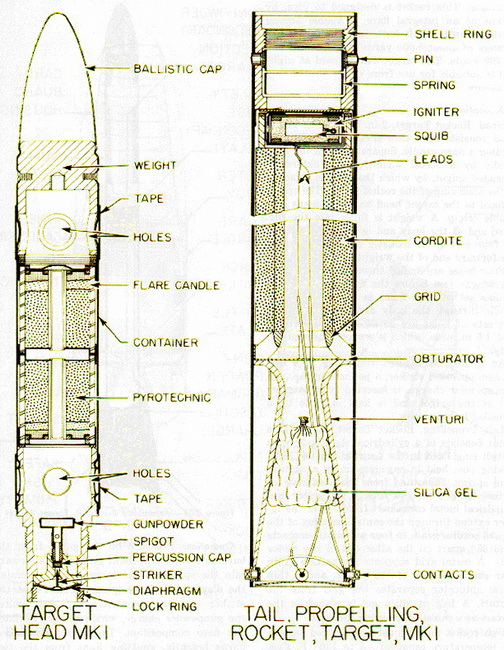
Head, Rocket, Target, 2-in., Mk I – The target head consists of a thin sheet-metal container holding in a flare candle. Separated from the flare candle by a steel washer is an externally threaded spigot, by which the head is attached to the shell ring of the roc-ket motor. The spigot is fixed to the target head body by means of a double crimp. A weight is fitted into the forward end of the body and is fixed to the body by four screws. A ballistic cap is crimped to the forward end of the weight. |
|
Four holes are drilled through the body and the weight just before the flare candle, and a similar set of four holes is drilled abaft the candle through the body and the spigot. The two sets of holes are covered with a strip of tape 1.5 in. wide, which is wrapped around the body. |
|
An igniter mechanism, consisting of a diaphragm-operated striker, a percussion cap, and a gunpowder charge, is inserted into the after end of the spigot and is held in place by a threaded locking ring. |
|
Tail, Propelling, Rocket Target, Mk I – This motor consists of a cylindrical steel body with a shell ring fixed in the forward end by eight locking pins held in engagement by a circular band spring. Separated from the shell ring by a steel, flanged support ring, is an igniter in a cylindrical metal container. Leads from the igniter extends through the central annulus of the cogged cordite grain to four automatic contacts fixed 45° apart on the after end of the motor body. A metal grid supports the cordite grain near the after end of the motor, and a thin metal obturator separates the grid from the venturi. A bag of silica gel is placed in the venturi as a moisture-proofing measure. |
|
The rocket motor must not be fired outside the temperature range of -5 to 120° F. Proposed new nomenclature for this motor is Motor, Rocket, 2-in., No. 4 Mk I. |
|
Operation: Pressure of the gases from the burning cordite propellant grain passes forward into the spigot of the target head, reversing the diaphragm of the igniter. This forces the striker into the percussion cap and ignites the gunpowder charge, which in turn initiates the flare composition. The flare composition burns brightly, emitting light from the two sets of holes drilled in the body of the target head. |
|
|
| Figure 201 – Assembled 2-in. U.P. Target Rocket |
|
|
| Figure 202 – 2-in. U.P. Target Rocket Components |
|
|