|
|
| BRITISH EXPLOSIVE ORDNANCE |
| Part 3 - Chapter 2 |
| High-Explosive Rockets |
|
Antisubmarine Rocket Assembly |
| Data |
| Depth Charge | ||
|
Over-all length |
37 in. | |
|
Diameter |
11 in. | |
|
Total weight |
260 lb. |
|
|
Explosive |
Amatol | |
|
Explosive weight |
180 lb. | |
|
Fuzing |
Depth Charge Pistols Mk XIV or XVI |
|
| Rocket Motor | ||
|
Over-all length |
20.25 in. | |
|
Diameter |
2.25 in. | |
|
Total weight |
6.0 lb. | |
|
Propellant |
Cogged cordite (SU/K/C029) | |
|
Propellant weight |
1.3 lb. | |
|
Burning time |
0.45 seconds at 60° F. |
|
|
General: This ammunition is designed for harbor defense purposes and will probably not be used afloat. |
|
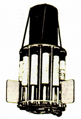
Description: The round consists of one Depth Charge Mk XI, without tail (See Part 1, chapter 9, Depth Charges), fitted with 12 Propelling Tails, Rocket, No. 5 Mk II. These motors are mounted in a cylindrical shell encircling the depth charge. The shell measures about 21 in. long by 17 in. external diameter, and weighs about 100 lb. The complete round assembled weighs about 375 lb. |
|
The round is fired electrically from a single-mount, trough-type launcher. The electri-cal cicuit is selectively arranged so that from 4 to 12 motors may be fired, giving ranges varying from 65 to 550 yd. in 50-yd. increments. Large fins may be fitted to the round, but at ranges under 300 yd. fins are usually omitted from the assembly. |
|
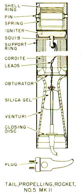
Tail, Propelling, Rocket, No. 5 Mk II – This motor consists of a cylindrical steel body with a shell ring fixed in the forward end by eight locking pins held in engagement by a circular band spring. A metal-cased igniter is located immediately behind the shell ring. An electric squib is inserted in the base of the igniter, the leads from the squib extending through the central annulus of the cogged cordite grain and the venturi, and ending in a two-pronged niphon plug. Behind the igniter, positioned by a metal support ring is located the cordite grain, which is supported at its after end by a metal grid. Separating the grid from the venturi is a thin metal tail obturator. The venturi is loacted in the after end of the motor body and contains a small bag of silica gel as a moisture-proofing measure. |
 |
| Figure 197 – Antisubmarine Rocket Assembly |
 |
| Figure 198 – Motor for Antisubmarine Rocket Assembly |
|
|