|
|
| BRITISH EXPLOSIVE ORDNANCE |
| Part 2 - Chapter 3 |
| Fuzes |
|
Nose Fuze No. 845 Mks I - IV (Obsolete) |
| Data |
| Bombs used in | G.P. 250-lb. Mks III and IV, G.P. 500-lb. Mks III and IV, G.P. 1,000-lb. Mk I, and G.P. 1,900-lb. Mk I. Will fit bombs which take any standard nose pistol |
| Action | Fires upon disturbance |
| Armed condition | When the vanes are up or are broken off after impact |
| Fuze used with | No. 37 Mks I - VI |
| Arming time | 20 seconds after impact |
| Vane span | 4.5 in. |
| Body diameter | 2.25 in. |
| Over-all length | 3.5 in. |
| Color | Unpainted steel |
|
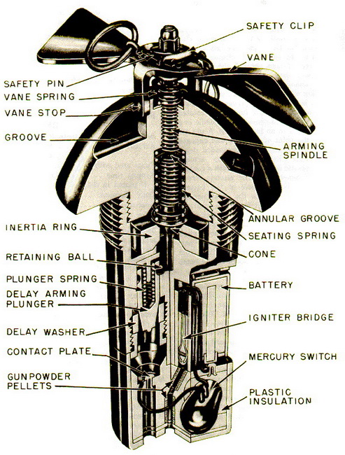
Description: The fuze consists of abody, arming vanes, and an electric circuit com-prising a dry cell, an igniter bridge, a sensitive mercury switch, and a delay arming switch. The upper part of the fuze body is ogival complete the streamling of the bomb. A safety clip, inserted between the vanes and the top of the arming spindle, depresses the vanes against the force of the van spring and prevents the vanes from rotating by mes-hing two vane stops with two grooves in the top of the fuze ogive. |
|
Attached to the vanes is an arming spindle, which is threaded down through the top of the fuze. Half-way down the arming spindle is located an annular groove, which inter-rupts the threading of the spindle. The lower end of the spindle is enlarged to prevent its falling completely away from the fuze when rotated by the vanes. Located beneath the spindle is a cone, which rests in an inertia ring. A pin extends from the point of the cone and engages the retaining ball of the spring-loaded delay arming plunger. Below the delay arming plunger is a plastic delay washer with a contact plate located beneath it. The electric circuit leads from the positive pole of the battery through the fuze body to the delay arming plunger, where the circuit is broken until the plunger makes contact with the contact plate. From the contact plate, the circuit leads to the mercury switch, and from the mercury switch through the igniter bridge to the negative pole of the 1.5-volt dry-cell battery. Leading from the igniter bridge to the exploder in the bomb is a series of gunpowder pellets. |
|
Operation: When the bomb is loaded aboard the plane, the safety pin is removed from the arms of the safety clip. On release from the plane, the safety clip is removed. The vane spring forces the vane stops up out of their grooves, and the vanes are allo-wed to rotate and thread the arming spindle upward until its enlarged end engages the internal shoulder of the fuze body. The momentum of the rotating vanes is then suffi-cient to snap the arming spindle at the weakened groove. The upper portion of the spindle and the vanes then fall away from the fuze. The cone is now held downwards only by the seating spring. On impact, the cone and attached pin are forced upward against the spring, and the retaining ball moves out of engagement with the delay arming plunger, which is forced by its spring against the delay washer. After 20 seconds, the delay washer is pierced and the plunger makes contact with the contact plate, thus completing the firing circuit except for the mercury switch. Any subsequent movement will cause the mercury to flow, complete the circuit, and fire the fuze. |
|
Remarks: The Fuze No. 845 Mk II is like the Mk I except that it has a spring-link type safety clip, and the nose of the fuze is shorter. |
|
|
|
Figure 156 - Nose Fuze No. 845 |
|
|