|
|
| BRITISH EXPLOSIVE ORDNANCE |
| Part 2 - Chapter 3 |
| Fuzes |
|
Tail Fuzes No. 30 Mks I - III, and No. 37 Mk I (Service) |
| Data |
| Bombs used in | No. 30, S.A.P. 250- and 500-lb. Mks II - IV; No. 37, A.P. 2,000-lb. Mks I - III |
| Action | 0.1 sec. delay on impact; No. 30 Mk I only has additional special delay of 0.01 sec. |
| Armed condition | No external indication |
| Fuzes used with | None |
| Arming time | 480 vane revolutions (approx.) |
| Over-all length | No. 30, 14.5 in.; No. 37, 23.3 in. |
| Body diameter | No. 30, 2.75 in.; No. 37, 2.75 in. |
| Color | No. 30, brass and unpainted metal; No. 37 black |
|
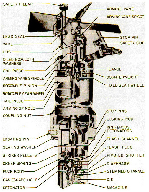
Description: These fuzes are fundamentally the same, the principal difference bet-ween the No. 30 and No. 37 being in length, and the fact that, because of its additional length, the No. 37 arming spindle is fitted with two universal joints. The No. 30 Mk II fuze body is of tubular section and is externally threaded at one end to receive a coupling nut, which secures a tubular tail piece to the fuze body. Screwed into a flange on the fuze body is a locating pin for insertion into the slot in the exploder container of the bomb. The lower end of the fuze body is closed by a C.E. filled magazine, which has a thin bottom wall. The upper end of the magazine is closed by a diaphragm having a firing channel communicating with the magazine, the channel being stemmed with C.E. |
|
An arming vane is secured to the end of the arming-vane spigot, and a flanged arm-ing-vane spindle supports a rotatable pinion and counter-weight. The pinion meshes with two gear wheels, one fixed to the tail piece and having 59 teeth, the other engaging the arming spindle and having 60 teeth. Secured to the arming spindle is a locking rod pro-jecting into and retaining a pivoted shutter in the unarmed position. The shutter contains a detonator, and has a spring which forces it about its pivot to line up with the firing channel when the locking rod is withdrawn. |
|
The fuze has two identical delay mechanisms, each consisting of a striker, a creep spring, an igniferous detonator, a delay pellet, and an adjoining powder pellet, so positi-oned that the powder pellet extends over a flash channel, and that one end of the delay pellet adjoints a firing hole, which opens into the bottom of the striker chamber. The stri-kers are retained in the unarmed position by the arming spindle, which is screwed into the sides of the strikers. Stop pins prevent the arming spindle and the strikers from jam-ming. |
|
Operation: When the fuzed bomb is released, the safety clip is pulled free and the arming vanes rotate. The pinion is revolved around the fixed and rotatable gears, and, because of the difference in the number of teeth, rotates the movable gear and hence the arming spindle once every 60 vane revolutions. As the arming spindle is rotated, it unthreads from the strikers and draws the locking rod out of the shutter. When the lock-ing rod clears the shutter, its spring forces it about its pivot, aligning the detonator with the firing channel. The shutter is locked in this position by a pivoted, spring-controlled locking pawl, which snaps into position behind the shutter. The pawl is locked by a spring-actuated plunger, which moves down into a groove in the pawl. As the arming spindle clears the strikers, it slides upward through the rotatable gear wheel. The fuze is now armed. |
|
On impact the strikers move down, overcoming the creep springs, and fire the ignife-rous detonators. The flashes from the detonators pass through the firing holes and ignite the delay pellets. which in turn ignite the powder pellets. The flashes from the powder pellets pass thriugh the flash channel and the flash plug, and ignite the detonator, which, by detonating the C.E. in the stemmed channel, fires the C.E. in the magazine. Impact of the fuzed bomb with the the light superstructure of a ship, or with the surface of the sea, is sufficient to cause the fuze to function. |
|
Remarks: The Fuze No. 30 Mk I includes a special and a normal delay. The arming mechanism is the same, but the delay mechanism differs in that the striker for the spe-cial delay is supported by a shear wire when released by the screwed arming spindle. There is no creep spring beneath this pellet. The normal delay activates the fuze as des-cribed above, but the special delay functions when the fuzed bomb strikes one-inch mild steel plate with a velocity of 500 ft. per sec. When this occurs, the wire supporting the striker is sheared, and the striker moves against, and fires, the igniferous detonator be-low it. The flash from the detonator passes through the firing hole to the delay pellet, which ignites the powder pellet. The flash from the powder pellet passes through the flash channel and the flash plug and ignites the detonator, which fires the C.E. in the magazine by detonating the C.E. in the stemmed channel. |
|
The No. 30 Mk I* is the same as the Fuze Mk II, above. The No. 30 Mk III is similar to the Mk II, except that it is fitted with a stirrup and a packing washer, and has a fork se-cured to the safety clip to press the arming-vane spigot firmly against the packing was-her to form a water-tight joint while the fuzed bomb is being taxied over water. |
|
|
|
Figure 148 - Tail Fuze No. 30 Mk II |
|
|