|
|
| BRITISH EXPLOSIVE ORDNANCE |
| Part 2 - Chapter 2 |
| Pistols |
|
Depth Charge Pistol Mk X** (Obsolete) |
| Data |
| Bombs used in | Depth Charges Mk VII and Mk VIII |
| Action | Hydrostatic; variable settings of 50, 100 and 150 feet |
| Armed condition | No external evidence of arming |
| Body diameter | 3.48 in. |
| Over-all length | 16 in. |
| Color | Brass |
|
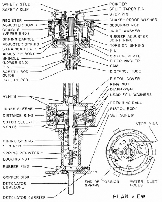
Description: The depth adjuster comprises a cylindrical body in which is housed an orifice plate contaning three leak holes of different sizes, corresponding to firing depths of 50, 100, and 150 feet. Located on top of the orifice plate are a strainer plate and an adjuster spring, which holds the strainer plate in position and the orifice plate on its seating. The orifce plate is mounted on a spindle, the lower end of which fits in a hole in the bottom of the adjuster body and is hollow and slotted to receive a safety rod. Fitted loosely on the upper end of the spindle is a spring barrel, an extension of which fits in a hole in the center of an adjuster cover. A pointer is secured to the spring-barrel exten-sion, and both extension and pointer are slotted for the use of a winding tool. A pin in the bottom of the springer barrel projects through the strainer plate into a hole in the orifice plate. Coupled to the bottom of the spring barrel at its lower end, and to the ad-juster cover at its upper end, is a torsion spring, which tends to rotate the orifice plate and the pointer in a clockwise direction. |
|
The adjuster body is closed by the adjuster cover. Marked on the cover the word SAFE, and the depth setting numbers 50, 100, and 150. At the side of the word SAFE is a hole to receive the safety stud, and beside each number, a hole for a stop pin. Three inlet holes in the cover allow water to enter the adjuster body. In the safe position the pointer is secured to the safety stub by a safety clip. |
|
In the bottom of the adjuster body is a hole which allows water to enter the primer tube of depth charge, when any particular leak hole in the orifice plate is in line with it, but it is blanked by a plain section of the orifice plate when the depth adjuster is set at safe. |
|
Screwed to a spigot on the bottom of the adjuster body is a safety-rod guide to which is screwed the upper end of the distance tube. This tube houses a safety rod, through the upper end of which is inserted a pin which engages in the slots in the orifice plate spindle and also with two cams formed on the spigot on the bottom of the adjuster body. When the depth adjuster is set on SAFE, the safety rod is held in the lowered po-sition. |
|
The pistol comprises a cylindrical body which houses a firing mechanism. The body is closed at the upper end by a pistol cover, which is screwed to the lower end of the dis-tance tube and is secured in the pistol body by a ring nut. In the pistol cover and the pistol body, respectively, slide an inner and outer flanged sleeve, each sleeve having a hollow stem, the stem of the outer sleeve sliding over that of the inner. Between the flanges of the sleeve is a double-acting rubber diaphragm, the two discs of which are se-parated by a distance ring. Between each disc of the diaphragm and the distance ring is a lead-foil washer to prevent adhesion. The pistol cover, pistol body, and sleeves have air vents to equalize the internal pressure. The pistol body and distance ring both have six evenly spaced holes through which is transmitted the pressure which expands the diaphragm, thereby moving the sleeves in opposite directions. The fact that the inner and outer sleeves move in opposite directions to operate the firing mechanism renders the pistol inertia-proof, as no shock can produce these opposed motions simultaneously. The striker slides in the stem of the inner sleeve and is held cocked by two balls, loacted in the inner sleeve, engaging in a groove in the striker. When the depth adjusted is set on SAFE, the striker is prevented from moving upwards by the safety rod. |
|
Operation: On release from the plane, the safety clip is pulled free by the fuze-sett-ing control link. When the depth charge becomes submerged, water enters the adjuster body and passes through the strainer plate, the patriuclar leak hole in the orfice plate, and the hole in the bottom of the adjuster body, to the primer tube, where pressure is built up. While the depth charge is sinking, the increased pressure is transmitted through the holes in the pistol body and distance ring to the two discs of the diaphragm, which beginns to expand and move the sleeve, and striker, compressing the firing spring. When the depth charge has sunk to its set depth, the two sleeves have moved through their maximum travel, and the balls are forced out into a recess formed in the stem of the outer sleeve, thereby releasing the striker, which fires the detonator. |
|
Remarks: Some Depth-Charge Pistols Mk X** have an adjuster with holes drilled for 250, 350, and 500 feet. This pistol though no longer used for aircraft depth charges, re-mains the standard depth-charge pistol for charges dropped by surface craft. An identi-cal copy of this pistol has been developed and used by the Japanese. |
|
|
|
Figure 143 - Depth Charge Pistol Mk X** |
|
|