|
|
| BRITISH EXPLOSIVE ORDNANCE |
| Part 2 - Chapter 2 |
| Pistols |
|
Tail Pistols No. 54 Mk I and No. 60 Mk I (Service) |
| Data |
| Bombs used in | No. 54 – G.P. 250- and 500-lb. Mk IV; G.P.
1,000-, 1,900-, and 4.000-lb.; all M.C. bombs; S.A.P. 250- and 500-lb. Mk V;
A.P. 2,000-lb. Mk IV; and A.S. 100-, 250-, and 500-lb. Mk V. No. 60 – I.B. 400-lb. Mk I |
| Action | Instantaneous on impact; semi-all-ways action |
| Armed condition | When arming spindle is unscrewed from striker head |
| Fuzes used with | No. 54, Nose Pistols No. 27, 42, or 44; No. 60, none |
| Arming time | 15 arming-fork revolutions |
| Body diameter | 2.4 in. |
| Over-all length | 3.6 in. w/o striker guide |
| Color | Brass body. |
|
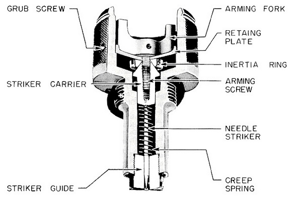
Description: The pistol consists of a brass body with a hollow cavity into which is placed the striker assembly, an inertia ring, a retaining plate, and an arming fork with a threaded spindle. The striker assembly is composed of a tapered striker head, bored and threaded internally to receive the arming spindle, and a needle striker, positively secured to the striker head and positioned by a striker guide threaded into the lower extension of the pistol body. A creep spring bears upwards against the striker head, and a guide pin, located in the pistol body and riding in a groove in the striker head, prevents the striker head from rotating. The body is recessed to permit downward movement of the striker head; and an internal shoulder is provided in the large hollow cavity to seat the retaining plate, which is held in place by three grub screws. The arming spindle is pinned to the arming fork, and threads through the retaining plate into the striker head. The inertia ring fits loosely under the retaining plate and is beveled internally to male with the conical shaped striker head. |
|
A special locking washer is used with this pistol. This washer has four studs bent downward in such a manner that they engage in recesses in the exploder container. When the pistol is fully screwed home, one of the 19 external tabs of the locking washer is bent upwards to engage in one of the two grooves cut in the base of the pistol head. |
|
Operation: When the bomb is released, the arming vanes in the tail cone rotate, and thread the arming fork and attached spindle upwards. After approximately 15 revolutions, the arming spindle is completely withdrawn from the striker head and inertia ring, and the striker head is now held up only by the creep spring. On impact, the striker head over-comes the resistance of the creep spring, and drives the needle striker into the detona-tor. |
|
If the bomb lands on its side, the inertia ring moves sideways, bearing against the be-veled top of the striker head and driving it downward against the creep spring, thus firing the detonator. |
|
Remarks: The Pistol No. 54 Mk I has been developed to replace the Pistol No. 30 for low-level attacks, when the bomb may be expected to make side or angle impact. Although resembling the Pistol No. 28 externally, this pistol is considerably greater in dia-meter than the No. 28. It is restricted to employment in low-level bombing operations on fighter/bomber aircraft only. Therefore only sensitive-type detonators of 11 seconds de-lay or longer may be used. |
|
Tail Pistol No. 60 Mk I is identical to the Pistol No. 54 Mk I, except that the arming spindle is considerably lengthened and the arming fork is replaced by a T-bar firmly atta-ched to the top of the spindle. |
|
|
|
Figure 140 - Tail Pistol No. 54 Mk I |
|
|