|
|
| BRITISH EXPLOSIVE ORDNANCE |
| Part 2 - Chapter 2 |
| Pistols |
|
Nose Pistol No. 27 Mks I, I* and II and No. 42 Mks I and II (Service) |
| Data |
| Bombs used in | G.P. 250-lb. Mk IV, G.P. 500-lb. Mk IV, G.P. 1,000-lb. Mks I and II, G.P. 1,900-lb., G.P. 4,000-lb., all M.C. and H.C. bombs and I.T. 60-lb. |
| Action | Instantaneous on impact |
| Armed condition | When the vane boss is 3/16 in. above top of flange on body |
| Fuzes used with | Pistols Nos. 28 and 30 Tail |
| Arming time | 3 vane revolutions |
| Vane span | 4.0 in. |
| Body diameter | 1.9 in. |
| Over-all length | 4.2 in. |
| Color | Aluminum or brass vanes, brass body, and steel striker and pres-sure plate. The No. 42 has a green painted vane cap |
|
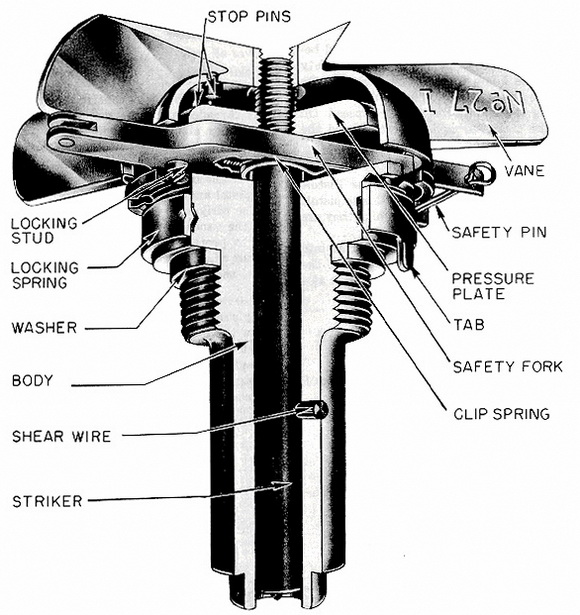
Description: The construction of these pistols is essentially the same, the differences being noted below. The brass body has a flange on the top, which has eight notches to receive the stop pin of the safety pin. The lower end is reduced in diameter to receive the detonator, with which it makes a friction fit. The pistol body is bored centrally to re-ceive the steel striker, which is threaded on one end, and onto which are screwed the pressure plate and the vane cap. Both the pressure plate and the vane cap have stop pins to prevent the cap from being screwed down and binding on the plate. A shear wire through the striker and the pistol body holds the striker cap. |
|
The vane cap is aluminum, with five vanes, and is cast in one piece. On one of the vanes is stamped the number and mark number of the pistol. The vane cap is riveted to a brass vane bush, which screws onto the striker. Opposite sides of the vane cap are cut away to receive the brass safety clip, having a steel clip spring. The latter fits around the striker and holds the safety clip in place, while the stop pin on the safety clip fits into one of the eight notches in the flange on the pistol body. The safety pin goes through the ends of the arms of the safety clip. A tab locking device fits around the pis-tol body below the notched flange. |
|
Operation: The safety pin is pulled out before the bomb is put into the plane, and the safety clip is removed when the bomb is released. The vane cap is now free to rota-te, and after approximately seven revolutions, falls off. The pistol is now armed. On im-pact, the shear wire is sheared and the firing pin hits the detonator. |
|
Remarks: The Pistol No. 27 Mk I has a bronze shear wire and blunt firing pin. The No. 42 differs from the No. 27 in that it has an aluminum shear wire, a sharp firing pin, and a green vane cap, vanes, and locking ring. The No. 42 is now replacing the No. 27. |
|
|
|
Figure 127 - Nose Pistol No. 27 Mk I |
|
|