|
|
| BRITISH EXPLOSIVE ORDNANCE |
| Part 2 - Chapter 2 |
| Pistols |
|
Nose Pistol No. 16 (Obsolete) and No. 16 Mk I (Obsolescent) |
| Data |
| Bombs used in | H.E. 20-lb. Mk I |
| Action | Instantaneous on impact |
| Armed condition | When striker can be seen through central hole in base of fuze |
| Fuzes used with | None |
| Arming time | From 5 to 25 vane revolutions depending on setting |
| Vane span | 3.1 in. (5 vanes) |
| Body diameter | 3.3 in. |
| Over-all length | 3.3 in (less booster) |
|
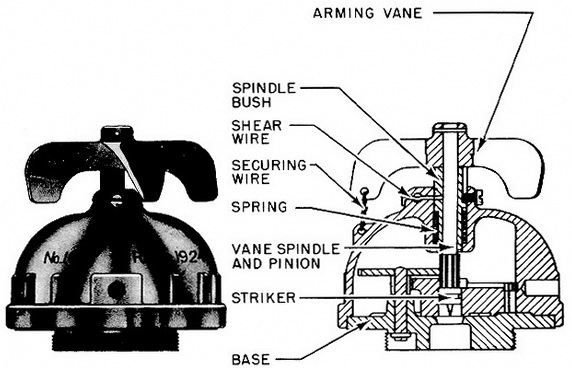
Description: The body is a hollow, dome-shaped casting, recessed at the bottom to take the base, which is secured to the body by three screws. The top of the body has a boss bored to take an arming-spindle bush, which houses an arming spindle and pinion. Located between a shoulder in the bore of the boss and a shoulder on the bush is a spring, which tends to keep the bush from moving inwards should the shear wire be bro-ken. The bush has a slot cut in its side, to accommodate a guide screw. The arming vane is locked by a securing wire, which is threaded through a hole in the arming vane and a hole in lug cast on the body. The base is threaded at the lower end to screw into the bomb body, and is bored centrally to allow the striker access to the detonator in the bomb. |
|
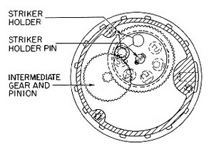
The safety gear train is formed by the arming spindle and a pinion, which engages with an intermediate gear and pinion. The pinion of the intermediate gear engages with teeth cut on the striker holder, which is in the form of an interrupted-tooth gear wheel, and has a triangular-shaped stop on its upper surface which contacts the arming spindle and pinion after a predetermined number of revolutions of the arming vane. |
|
The striker is press-fitted into a hole in the striker holder adjacent to the triangular stop, and the striker is in alignment with the arming spindle. The striker holder has the numbers 5, 10, 15, 20, and 25 marked on its under side on the same pitch circle as the hole which houses the striker. When any one of these numbers is opposite the central hole in the base, approximately that number of revolutions of the arming vane will be re-quired to bring the striker opposite the central hole in the base. The normal setting is 25. The striker holder rotates on a striker holder pin, which is riveted to the base of the pis-tol. The striker holder is retained on the pin by a split pin. |
|
Operation: On release of the bomb, the vanes rotate and act through the arming spindle and pinion the intermediate gear and its pinion in a counterclockwise direction. The pinion on the intermediate gear rotates the striker holder in a clockwise direction. After a predetermined number of revolution, the triangular stop on the upper surface of the striker holder comes into contact with the arming spindle pinion, aligning the striker with the arming spindle and hole in the base, and preventing further rotation of the stri-ker holder. On impact, the arming vanes, arming spindle and pinion, and spindle bush are forded inwards against the spring, breaking the shear wire. The inner end of the arming spindle and pinion forces the striker into contact with the percussion cap of the detona-tor in the bomb. |
|
Remarks: If the pistol is not in the bomb, visual inspection through the hole in the base will indicate the number of vane revolutions required to align the striker with the pinion and the hole in the base, since the numbers 5, 10, 15, 20, and 25 are marked on the bottom of the striker holder and are visible when opposite the hole in the base. |
|
The Psitol No. 16 Mk I was formely designated as the Pistol No. 7 Mk I. |
|
|
|
Figure 120 - Nose Pistol No. 16 Mk I |
|
|
|
Figure 121 – Safety gear train of Nose Pistol No. 16 Mk I |
|
|