|
|
| BRITISH EXPLOSIVE ORDNANCE |
| Part 1 - Chapter 21 |
| Cluster Projectiles |
|
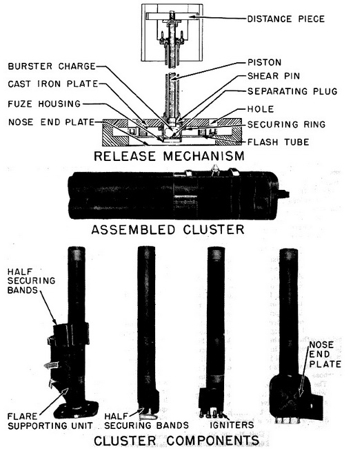
Cluster Projectile 400-lb. No. 3 Mk I (Service) |
| Data |
| Fuzing | Nose Fuze No. 860 |
| Color markings | Black over-all |
| Contents | Four 7-in. hooded flares |
| Over-all length | 72.5 in. |
| Body diameter | 18 in. |
| Total weight | 400 lb. |
|
Description: The cluster projectile consists of a flare-supporting unit, heavy nose, half securing bands, and the hooded flares. The flare-supporting unit consists of a square cast-iron plate, on which is painted a narrow white alignment strip, and a steel tube to which is welded a suspension web. The rear end of the tube is flanged, and four equispaced pins are riveted to the flange. External threads on the fuze housing receive the plate-securing ring, which secures the plate to the tube. The tube is also internally threaded at the nose end to receive the fuze and a centrally drilled separating plug. |
|
Four flash channels are drilled through the walls of the fuze housing immediately ab-ove the separatring plug. Four flash tubes lead from these flash channels to the four equispaced holes in the plate drilled to receive the flare igniters. The piston, flanged at the protruding tail end, is housed in the tube and retained in position at the nose end by two shear pins. A space between the nose end of the piston and the centrally drilled se-parating plug forms a burster chamber, which is filled with a small fabric bag containing 80 grams of gunpowder when the cluster is fuzed. The heavy cast-iron nose, on which is painted a white aligmnent strip, and to which the flare supporting unit is bolted, is slot-ted to receive the flash tubes and the Fuze No. 860. The nose end plate is retained in position by the fuze. The four flares are fitted with special ignites instead of fuzes, and are retained in position in the cluster by half securing bands. The igniters are located in the drilled holes in the plate. |
|
The four half securing bands of the flare securing unit are seated on the flange, and each is retained in position by a socket, welded to the outside of the band, engaging with a corresponding dowel pin. The sockets are covered by metal bridges in which are cut horizontal slots to receive the flange of the piston. This prevents premature displa-cement of the flares. The four remaining half securing bands are placed in position round the flares and bolted to the other half bands. A cruciform distance piece is bolted to the tail end of the piston. |
|
Functioning: On release from the aircraft, the cluster falls in a normal manner until the fuze functions. The flash from the fuze magazine passes through the flash cannels and the flash tubes to activate the igniters, and through the separating plug to the burster charge. The explosion of the burster charge forces the piston towards the tail end of the cluster to sever the shear pins and to lift the half securing bands off the do-wel pins by means of the flange of the piston engages in the bridges. The four flares are thus lifted off the plate of the flare supporting unit. A three-second delay in the flare ig-niters allows the cluster to distintegrate before the flares function. |
|
|
|
Figure 105 - Cluster Projectile 400-lb. No. 3 Mk I |
|
|