|
|
| U.S. EXPLOSIVE ORDNANCE |
| PART 7 - GUIDED MISSILES AND FUZES |
| Chapter 21 - MISSILES |
| Section 5 - SIMILAR PROJECTS |
|
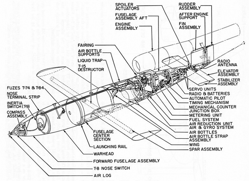
JB-2 (A.A.F.) or "Loon" (BuAer) - A Modification of the German V-1 |
|
Over-all length |
27 feet 1.1 inches |
|
Span |
17 feet 8.1 inches |
|
Total weight, pounds |
5,025 |
|
Warhead (T9) |
|
|
Weight, pounds |
2,100 |
|
Filling, pounds |
1,875 Tritonal |
|
Fuzing |
2,000-lb. G.P. Bomb AN-M66 |
|
Nose Switch |
T8 |
|
Mechanical Fuze |
T715 |
|
Electrical |
T705 |
|
Impact Switch |
T9 |
|
Destructor |
T15 |
|
General: The JB-2 and "Loon" are copies of the German V-1, with modifications. As fas as the ordnance components are concerned, the Army and Navy modifications are the same. |
|
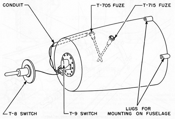
Warhead: The warhead is an aluminum-encased charge of Tritonal. The case is 3/8-inch thick and is bolted to the fuselage abaft the nose piece by four lugs. |
|
Destructor T15: At the appropriate distance from the target, as determined by the Veeder Root Counter, an electrical contact is closed, which sets off the electric blasting caps in the Destructor T15, igniting the small charge and blasting apart the two junc-tions in the wing spar. The spar breaks; the wings come off; and the missile is forced in-to the dive toward its target. |
|
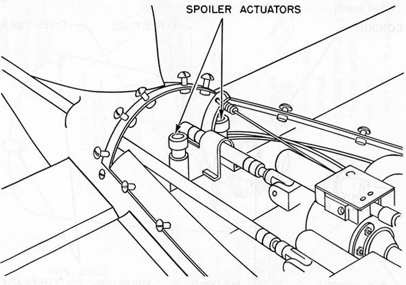
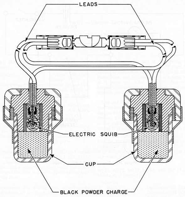
Presiously, the missile was put into its dive by the action of the Spoiler Actuators T1. These were small steel bullet-like cups filled with black powder and an electric squib. When activated by the Veeder Root Counter, they were fired down two vertical tubes in the tail section, releasing a spring-loaded knife arm which cut the rubber hoses from the servo motors to the controls; and, at the same time, the spring pulled the elevators down, putting the bomb into its dive. |
|
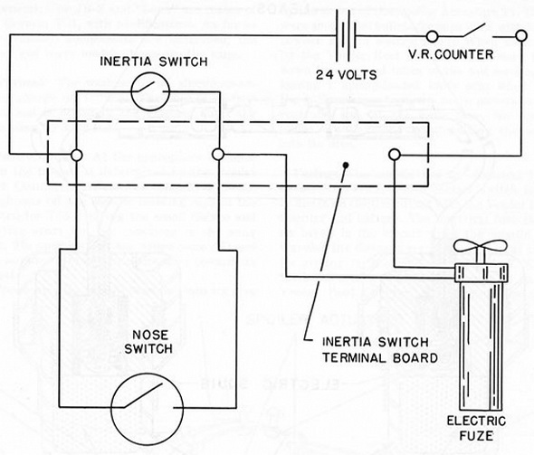
Fuzing: The missile has an electrical fuze, an inertia switch, and a contact switch in-terlocked in an electric circuit with the Veeder Root Counter and battery. The electrical fuze closes its break in the circuit when the missile has traveled the distance set in the fuze gear train for arming (in the T705, 3 to 50 miles). When the bomb is at a prescribed distance set on the Veeder Root Counter, the counter closes its switch in the firing ciruit and the circuit is ready for impact. When the bomb hits, either the Nose Switch T8 or the Inertia Switch T9 can complete the circuit, firing the booster in the electric fuze and setting off the warhead. In case the electrical firing circuit does not function properly, the mechanical fuze can detonate the warhead. |
|
Previously, a "belly" switch was connected in parallel to the nose and inertia swichtes, but this switch is no longer used. |
|
Remarks: This missile uses liquid oxygen as fuel, this oxygen being highle explosive. |
|
Figure 391. JB-2 or "Loon" Missile |
 |
|
Figure 392. Warhead of "Loon", with Fuzes and Switches in Place |
|
|
|
Figure 393. Location of Spoiler Actuators in "Loon" |
|
|
|
Figure 394. Spoiler Actuators T1 |
|
|
|
Figure 395. Diagram of JB-2 Fiirng Circuit |
|
|
|
|