|
|
| U.S. EXPLOSIVE ORDNANCE |
| PART 5 - MINES |
| Chapter 16 - FUZES AND FIRING DEVICES |
|
Combination Firing Device M1 (Obsolescent) |
|
General: The Combination Firing Device M1 is designed for firing explosive charges either by means of a trip wire or by pressure. When the device is employed in the Anti-Personnel Mine M2 or M3, an igniter or blasting cap is attached to the base and the as-sembly is designated Fuze, Mine, M2; M2A1; M3; or M3A1. |
|
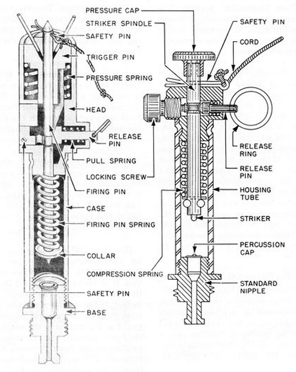
Description: The principle parts of the device are the body, striker spindle, pressure cap, locking screw, release pin, and standard nipple base. The pressure cap is press-fit-ted onto the top of the striker spindle, which extends into the body and is under tension of the firing-pin spring. The striker spindle has a circumferential groove to receive the locking screw and release pin, and is drilled to receive the safety pin below the pressure cap. The base, containing the priner, has an extension to which an igniter or blasting cap may be attached. |
|
Modification: Bending beyond seven degrees has caused the striker spindle to break at the point of the groove. To correct this defect, later productions will have the safety pin 1/3 inch to 3/16 inch below the point of the assembled firing pin instead of through the top portion of the striker spindle. |
|
Anti-Personnel Mine M2: When the Firing Device M1 is employed in this mine, an ig-niter is attached to the base and the assembly is designated Fuze, Mine, Anti-Personnel, M2. The Fuze M2 as modified with the safety pin below the striker spindle is designated Fuze, Mine, Anti-Personnel, M2A1. |
|
Anti-Personnel Mine M3: When the Firing Device M1 is employed in this mine, a blas-ting cap is crimped to the base and the assembly is designated Fuze, Mine, Anti-Person-nel, M3. The Fuze M3 as modified with the safety pin below the striker spindle is desig-nated Fuze, Mine, Anti-Personnel, M3A1. |
|
Operation: When the igniter or blasting cap has been attached to the base and in-serted in the charge, the locking screw is backed off so that it is no longer engaged in the groove in the striker spindle. The safety pin is then removed. If the safety pin binds, it is quite possible that the release pin is not properly engaged in the groove in the arm-ing spindle, and the device must be checked carefully. When the safety pin has been re-moved, the only thing preventing the striker spindle from being forced toward the per-cussion cap by its spring is the release pin, which is spring loaded inward. The device is now armed and can be fired either by pressure on the pressure cap or by pull on the re-lease ring. If over 20 pounds of pressure is exerted on the cap, it will be sufficient to force the release pin out against its spring; if a pull of three to six pounds is exerted on the trip wire, the release pin will be pulled free of the groove in the arming spindle and the striker will be forced against the percussion cap by its spring. |
|
Remarks: This firing device is used almost exclusively with the Anti-Personnel Mines M2 and M3. |
|
Figure 251. Combination Fuze M6 (left) and Combination Firing Device M1 (right) |
|
|
|
|