|
|
| U.S. EXPLOSIVE ORDNANCE |
| PART 3 - PYROTECHNICS |
| Chapter 8 - AIRCRAFT PYROTECHNICS |
| Section 3 - NAVY FLARES |
|
Mk 11 Mod 0 |
|
Length, inches |
37.75 |
|
Diameter, inches |
5.37 |
|
Weight, pounds |
30 |
|
Burning time, minutes |
3 |
|
Color |
Pale yellow |
|
Intensity, candlepower |
1,000,000 |
|
Delay, seconds |
90 - 180 |
|
Minimum release altitude, feet |
2,500 - 4,000 |
|
Use: The NAVY Flare Mk 11 will supplement the AN-Mk 8 for night antisubmarine war-fare. |
|
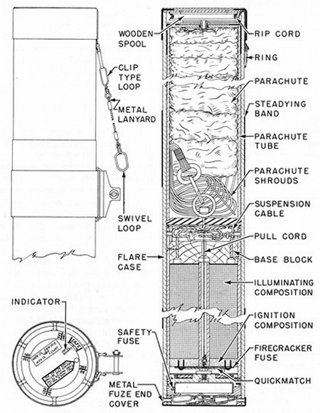
Description: The shellac-impregnated chip-board case of this flare has two metal steadying bands fastened to it and is closed at the parachute end by a chip-board disc held in place by a gummed cloth and sealed with paraffin. The rip cord is wound around a spool at the parachute end of the flare, and is attached to the parachute tube through a release key. The parachute and parachute shrouds are enclosed in the parachute tube. The shrouds are attached to a suspension cable, which is attached to the illuminant as-sembly. |
|
The fuze end of the flare is closed by a metal fuze and a cover which must be remo-ved when setting the fuze. Immediately below the cover is a firing lanyard with a swivel loop on one end and a clip-type loop on the other. |
|
The selective-delay ignition device is similar to the fuze used in the Mark 5 and Mark 6 types of aircraft parachute flares, the chief difference being that the fuze is initiated by a pull cord running through the center of the illuminant instead of by a firing lanyard. The pull cord is attached to the suspension cable. A safety screw keeps the firing lever of the fuze in position during shipping. A friction type snubber is employed at the lower end of the suspension cable. |
|
Operation: The metal fuze-end cover is removed and the firing lanyard withdrawn. The clip-type loop or the metal lanyard is attached to the arming wire retainer of the launching gear. A selective delay setting is made by pulling up on the index pin, turning the indicator to the required delay, and then releasing the index pin. The safety screw is removed. |
|
As the flare falls away from the aircraft, the swivel loop of the firing lanyard is held by the arming-wire retainer. The rip cord, which is fastened to the metal lanyard through the clip-type loop, unwinds from the wooden spool inside the end of the flare casing, thus tearing away the end of the flare casing. The rip cord then pulls out the spool and the parachute tube containing the parachute. The spool falls away. Since the parachute tube is held by the rip cord, the pyrotechnic candle and flare case fall away. The weight of the candle pulling on the suspension cable and parachute shrouds draws the para-chute out of the tube. When the parachute and shroud lines are fully extended, the re-lease-key cord becomes taut and pulls one end of the release key down. This allows the rip cord to pull through the key and become detached from the parachute and the tube, which falls clear. The rip cord and metal lanyard are retained by the aircraft. The para-chute opens and suspends the flare 30 to 50 feet below the aircraft. The parachute pulls the candle out of the flare case, which falls free. |
|
The selective-delay ignition device functions in a manner similar to the fuze used in the Flares Mk 5 and Mk 6. The fuze is initiated by a wire pull cord which passes through a hole through the center of the candle. The pull cord is attached to the suspension cable in such a manner that it is pulled away from the primer and then released, striking the primer and igniting the powder pellets in the fuze plunger. The burning powder forces the pointed end of the plunger into the Bickford Fuse which is ignited by flame through holes in the plunger. The time fuse ignites the quick match under the fuze block, which in turn ignites the quick match and firecracker fuse stapled to the ignition composition. The igni-tion composition ignites the candle. The gases generated by the burning candle. The ga-ses generated by the burning candle blow the fuze assembly off from the end of the py-rotechnic candle, and the fuze falls clear. |
|
Remarks: This flare differs from the AN-Mk 8 and Mods in that there is a selective de-lay between the opening of the parachute and ignition of the pyrotechnic candle. The selective delay allows a single patrol plane to drop a flare near the target and then get into position for the attack before the flare discloses his position. |
|
Figure 183. Flare Mk 11 Mod 0 |
|
|
|
|