|
|
| U.S. EXPLOSIVE ORDNANCE |
| PART 3 - PYROTECHNICS |
| Chapter 8 - AIRCRAFT PYROTECHNICS |
| Section 3 - NAVY FLARES |
|
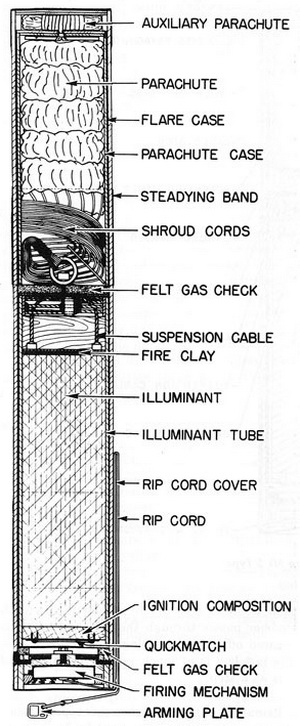
Mk 6 and Mods and AN-Mk 6 Mod 5 |
|
Length, inches |
37.75 |
|
Diameter, inches |
5.4 |
|
Weight, pounds |
30 |
|
Burning time, minutes |
3 - 3.5 |
|
Light intensity, candlepower |
1,000,000 |
|
Color |
Yellow |
|
Maximum release altitude, feet |
3,500 - 15,000 |
|
Rate of fall after ignition, ft./min. |
450 |
|
Use: These flares are used to illuminate a large area for reconnoitering and bombing, and also as a blinding effect on the operators of antiaircraft weapons. |
|
Description: The complete flare consists of the illuminant, a parachute, and an auxi-liary parachute contained in a shellac-impregnated chip-board case. The case is closed on the parachute end by several layers of chip-board discs held in place by gummed cloth tape and sealed with paraffing, and on the illuminant end by an Ensign Bickford time fuse and a metal cover. To the snap cord of the Ensign Bickford fuse is attached the rip cord, which is taped down along the side of the flare case. There are two metal steady-ing bands around the case, against which the steadying forks or sway braces of the bomb racks rest. The flare is issued in a waterproof metal container, and should be kept there at all times when not installed in an aircraft. |
|
Operation: When the flare is released, the arming plate is retained by the plane and the rip cord is torn from the side of the case, flipping the metal cover off the Ensign Bick-ford fuse. The operation of the fuse is the same as given in the NAVY Flare Mk 5. |
|
The gases evolved when the ignition composition begin to burn, force the end out of the flare case. Next, they expel the auxiliary parachute, the parachute in its case, and the illuminant. The flare case falls clear. The auxiliary parachute opens and retards the parachute in its case, to which it is attached, and the illuminant pulls the parachute out of its case. The auxiliary parachute and parachute case fall away, and the parachute opens. |
|
Remarks: This flare also incorporates a shock absorber as used in the NAVY Flare Mk 5, with either lead balls passing through a hole of smaller diameter than the lead balls, or a special connection utilizinh friction to absorb shock of the parachute opening. See Operation, p. 240. |
|
The Flare AN-Mk 6 Mod 5 differs from the Mk 6 and Mods in that the arming wire has swivel loops instead of an arming plate. |
|
Figure 180. Flare Mk 6 Type |
|
|
|
|