|
|
| U.S. EXPLOSIVE ORDNANCE |
| PART 2 - ROCKET AND ROCKET FUZES |
| Chapter 5 - ROCKET BODIES |
| Section 4 - NAVY ROCKETS |
|
5.0-inch A.R. with 5-inch motor |
|
Over-all length, inches |
69 |
|
Total weight, pounds |
140 |
|
Diameter of head, inches |
5.0 |
|
Length of head, inches |
20.3 |
|
Weight of head, pounds |
52 |
|
Motor length, inches |
51.4 |
|
Motor diameter, inches |
5.0 |
|
Velocity, ft./sec. |
1,350 |
|
Fuzes: |
Mk 50 Mod 0 and Mk 6 Mod 0 |
|
Nose Fuze Mk 148 |
|
|
Nose Fuze Mk 149 |
|
|
Base Fuze Mk 157 Mod 0 |
|
|
Base Fuze Mk 159 Mo 0 |
|
| Mk 6 Mod 1 | |
|
Base Fuze Mk 159 Mod 1 |
|
|
Base Fuze Mk 164 Mod 0 |
|
Head: The Head Mk 6 Mod 0 is filled with TNT and is equipped with a base fuze and a nose plug. When thus used, the head will have the penetration and fragmentation cha-racteristics at comparable velocities of the 5"/38 A.A. Common projectile, of which it is a modified design. All 5.0-inch Rocket Heads Mk 6 Mods 0 and 1 are shipped with a base fuze installed and staked in place. No attempt shall be made to remove the base fuze from the head prior to the firing. A metal cup-shaped thread protector covers the exter-nal threads on the base of the head and on the base fuze. |
|
The Mk 6 Mod 1 is similar to the Mk 6 Mod 0, with a gas seal added to the bomb-fuze seat. The 5.0-inch Body Mk 5 Mod 0 is the initial California Institute of Technology pro-duction, which was adopted by Bureau of Ordnance as the Mk 6 Mod 0. The two bodies are identical. |
|
The 5.0-inch Aircraft Common Mk 2 Mod 1 is a new head designed to achieve greater penetration. This penetration is expected to be two to three inches of homogeneous ar-mor plate at launching speeds of 1,500 feet per second. The head has a total weight of 48.1 pounds, is 14 inches long, and contains a filler of 2.66 pounds of Explosive "D". The nose is heavy and solid. A base fuze (the Mk 166 Mod 0) will be shipped installed. This head will fit any of the 5.0-inch motors. |
|
The Head Mk 2 Mod 2 has no adapter and has Acme threads; otherwise it is the same. |
|
Motor: The 5.0-inch Motor Mk 2 Mod 0 consists of a seamless steel tube with internal threads on both ends. Into the rear end is screwed the nozzle plate having eight nozzles arranged in a circle, and a central blow-out nozzle. The central nozzle is closed by a disc of 0.024-inch thick copper, insulated against the heat of the motor by asbestos and hard fiber plugs. The thickness of the disc is such that it shears and blows out at a pressure of approximately 2,400 pounds per square inch, which is the normal maximum motor pres-sure when the propellant grain is at a temperature of 100° F. If the pressure rises abovw this the disc and plug are ejected; this increases the usable temperature range of the rocket by about 40° F. |
|
Seven of eight nozzles are sealed individually by a light steel cup and sealing com-pound. The eight nozzle accommodates the electric connector cable, which is crimped into the steel nozzle closure. In shipment, a domeshaped steel shipping cap fits into the sleeve of the fin assembly, acting as an auxiliary seal and at the same time serving to enclose and protect the electrical pgtail in shipment. |
|
Lugs for attaching the fins are mounted on the nozzel end of the motor. The fins are shipped with the motor and are attached when the round is assembled. The fins are held in place by spring-loaded latches within the fin itself. The fin lugs and rear suspension lugs are welded to the bands of the fin assembly, which is slipped on over the nozzle end of the motor. The front lug band is strapped to the motor. The motor is shipped with lug attachments on the motor tube for use with Aircraft Launcher Mk 5 Mod 1. An extra rail-type lug is provided in the shipping box to adapt the rocket for use on the Aircraft Laun-cher Mk 4. |
|
The front end of the motor is sealed by a steel diaphragm equipped with a blow-out disc in the center to allow easy passage of the motor gases to the pressure-arming fuze in the base of the body. In shipment, a cylindrical metal thread protector extends into the motor the same depth as the body and seats on a felt rim glued to the diaphragm seal. |
|
The propellant is a grain of cruciform ballistite weighing 24 pounds. The grain is inhibi-ted on the outer web surface and is supported by a spacer and a steel grid at the nozz-le end. The propellant is ignited by a metal case igniter containing 35 grams of black powder. |
|
The 5.0-inch Motor Mk 2 Mod 1 was never produced. The Mk 2 Mod 2 differs in that the tail fins are welded to a sleeve which slips over the base of the tube and is clamped in place. The fin assembly is complete and separate from the motor. The rear suspension lug for use with the Launcher Mk 5 Mod 1 is on an independent band. The Mk 2 Mod 3, which will supersede the Mods 0 and 2, is similar to the Mod 2, except that the nozzle ring is of slightly different construction. |
|
The 5.0-inch Rocket Motor Mk 1 Mod 0, California Institute of Technology production, is the prototype of the Mk 2 Mod 0, Bureau of Ordnance issue. The two motors vary only in that the suspension lugs on the former are welded directly to the rocket motor. |
|
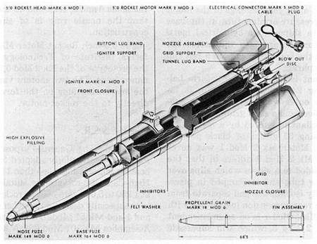
Figure 132. 5.0-inch A.R. with 5.0-inch Motor |
|
|
|
|