|
|
| U.S. EXPLOSIVE ORDNANCE |
| PART 2 - ROCKET AND ROCKET FUZES |
| Chapter 5 - ROCKET BODIES |
| Section 4 - NAVY ROCKETS |
|
3.5-inch Window |
|
Over-all length, inches (approx.) |
45.1 |
|
Weight, pounds |
32 |
|
Head length, inches |
23.2 |
|
Head weight, pounds (loaded) |
14.25 |
|
Motor length, inches |
23 |
|
Motor diameter, inches |
3.25 |
|
Width of tail fins, inches |
9.2 |
|
Length of tail fins, inches |
8.0 |
|
Fuze |
Base Fuze Mk 134 |
|
General: The window rocket is designed to be fired from Naval vessels equipped with a modification of the present shipboard launcher. The round carries a payload of paper-coated metal foil strips which are scattered in the air by a delayed-action charge. The payload is ejected at an altitude of 1,200 feet and range of 2,000 yards at 40° eleva-tion. |
|
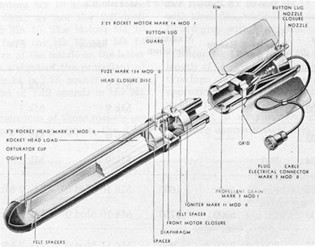
Description: The window rocket consists of a 3.5-inch Rocket Head Mk 10 Mod 0, Mk 14 Mod 0, or Mk 15 Mod 0 and a 3.25-inch Rocket Motor Mk 12 Mod 0, Mk 14 Mod 0, or Mk 14 Mod 1. The motor uses the propellant grain Mk 7 Mod 1, weighing 2.80 pounds. |
|
The rocket head contains a 3.5-inch rocket-head load - Mk 2, Mk 3, Mk 4, Mk 5, or Mk 8 - which is housed in a split steel ejection liner. It has a closure adapter on the after end, an obturator cup for sealing the front end, and a solid wood ogive cap retained by three aluminum rivets in the Mk 10, hollow steel friction fit in the Mk 14 and Mk 15. The closure adapter, which is welded to the after end, carries a copper diaphragm plate with a fring pin, and also serves as a chamber for the Cal. 32 blank cartridge which ignites the fuze. The Fuze Mk 134 consists of a plastic case containing a length of Ensign Bickford fuse and a 20-gram ejector charge of black powder. |
|
Rocket |
Length |
Number |
||
|
Mk 1 Mod 0 |
10" |
5,868 |
||
|
|
15" |
2,904 |
||
|
Mk 2 Mod 0 |
7.5" |
17,544 |
||
| Mk 3 Mod 0 |
12.5" |
5,310 |
||
|
|
15.5" |
3,462 |
||
|
Mk 4 Mod 0 |
6" |
11,676 |
||
|
|
9" |
5,863 |
||
|
Mk 5 Mod 0 |
1.87" |
76,800 |
||
|
Mk 8 Mod 0 |
400 ft. |
12 rolls |
|
All strips are 3/16 inches wide and 0.003 inches thick except the Mk 8, which is ½ inch wide. |
|
Operation: When the rocket is fired, gas pressure blows out the forward closure disc of the motor and exerts force on the diaphragm plate in the base of the motor adapter. The diaphragm collapses, and the firing pin is forced into the primer, firing the blank cart-ridge. The flash from the cartridge ignites the fuse, which burns for 15 seconds and then ignites the black-powder ejection charge. The firing of the ejector charge forces off the ogive cap and pushes the load forward out of the head. The strips are then dispersed. |
|
Remarks: The Motors Mk 12 Mod 0 and Mk 14 Mod 0 carry adjustable lug bands; the lugs are welded to the Motor Mk 14 Mod 1. The Mk 14 Mod 0 and Mk 14 Mod 1 have a metal base cap during shipping, to protect the electrical connector. |
|
The Head Mk 15 Mod 0 is one inch longer than the Head Mk 14 Mod 0. |
|
Figure 126. 3.5-inch Window Rocket |
|
|
|
|