|
|
| VT FUZES FOR PROJECTILES AND SPIN-STABILIZED ROCKETS |
| Chapter 2 - DESCRIPTION |
|
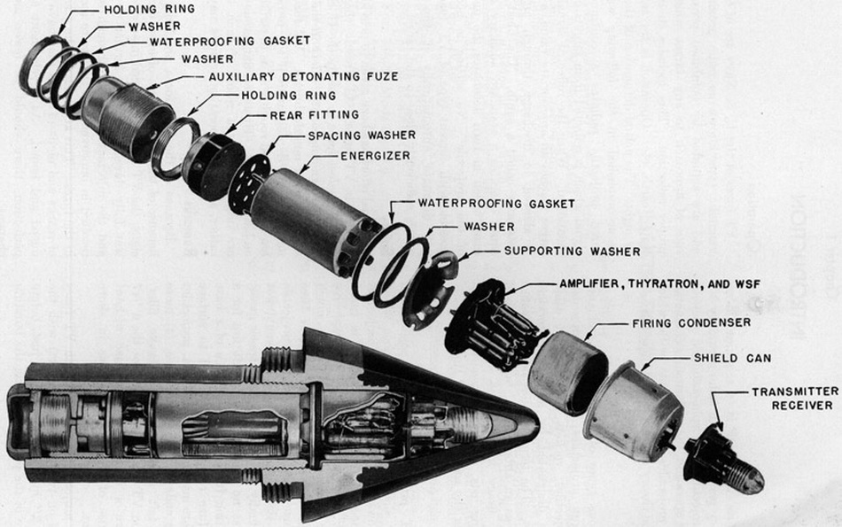
The VT fuze is composed of the following six main subassemblies or groups: |
|
1. The fuze body, or container |
|
2. Transmitter-receiver group, or oscillator group |
|
3. Amplifier, thyratron, and wave-suppression feature (WSF) group |
|
4. Reserve energizer |
|
5. Rear fitting |
|
6. Auxiliary detonating fuze. |
|
Since space limited, parts are located to achieve maximum space efficiency consistent with function. As a result, the firing circuit function is accomplished by components of the rear fitting and of the amplifier, thyratron, and WSF group. |
|
Figure 1. Cutaway and exploded view of a typical VT Fuze (VT Fuze Mk 53 Mod 5) |
|
|
|
The fuze body consists of a plastic nose ogive molded integral to a steel base ring, and a steel body cylinder with external left-hand threads at one end and internal left-hand threads at the other end. The nose base ring is threaded externally to fit the threads in the projectile nose and internally to recive the external threads of the body cylinder. |
|
The transmitter-receiver consists of a one-tube oscillating detector and an antenna. The antenna is either a conical metal cap molded into the plastic nose tip or a wire loop with-in the nose and coupled to the projectile which acts as the radiating antenna. The triode radio tube is set in a rubber socket for protection from shock and is mounted within a plastic form around which the transmitter-receiver coil is wound. The component parts are assembled in a plastic molding which is mounted on the shield can. The electrical leads connect to the antenna and the electrical circuit of the fuze. A ground is obtained for the electrical circuit through the shield can. |
|
When the energizer is activated, the tranmitter radiates a continuous radio wave into the space surrounding the fuze. |
|
The transmitter-receiver is capable at the same time of receiving the radio waves which are reflected from a target. As the fuze approaches a target, the intensity of the reflec-ted wave increases, producing what is known as a target signal. |
|
Amplifier, Thyratron, and Wave-Suppression-Feature (WSF) Group |
|
The parts of the amplifier, thyratron and WSF group, with the tubes in rubber sockets, are mounted on a plastic molding. They are contained within the shield can, with the an-nular firing condenser encircling the parts. Electrical leads connect with the transmitter-receiver and contact pins in the plastic base. |
|
Amplifier. The amplifier consists of two miniature pentods tubes with their associated resistors and condensers. Its function is to increase the amplitude of the target signal appearing at the output of the oscillator detector until it is capable of operating the fir-ing ciruit. Without amplification, the target signal, even on close proximity to the target, is of too low magnitude to perform useful service. |
|
Wave-Suppression Feature. The wave-suppression circuit is composed of a diode tube and various resistors and blocking or filter condensers. It decreases the sensitivity of the amplifier in the presence of steady signals. Thus it renders the fuze insensitive to the re-latively steady signals reflected from waves when the projectile is fired on a low trajec-tory. This tends to prevent the fuze from being operated by the reflected signals from waves. |
|
Firing Condenser. The firing condenser is an annular electrical condenser in the firing circuit. It provides a means of storing an electrical charge, received from the energizer, which can be rapidly expended, when called upon, to fire the squib. |
|
The thyratron is a triode radio tube with a small amount of argon gas in the bulb. It acts as an electronic switch to discharge the firing condenser through the squib when the projectile is near a target. When the projectile nears a target, the target signal received by the thyratron from the amplifier becomes of sufficient magnitude to lower the thyra-tron grid bias and allow tht condenser to discharge through the squib. The squib is explo-ded by the surge of current. |
|
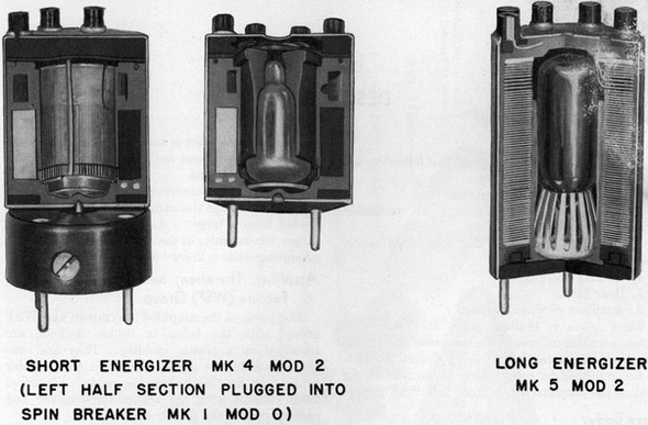
The reserve energizer is located in the fuze body cylinder, with its contact clips receiving the contact pins of the transmitter-receiver. It is the source of electric power for oper-ation of the fuze. It is composed of three compact wet-type batteries; the "A" battery, "B" battery, and "C" battery. The electrolyte for the batteries is contained in a glass am-poule mounted in a soft plastic cup in the central cavity of the energizer. The ampoule rests on the breaker which fits into the bottom of the plastic cup. The plates of a long-type energizer such as Energizer Mk 5 Mod 2 (fig. 2) are made up of flat zinc washers, coated on one side with carbon and assembled in a stack surrounding the ampoule. They are separated from each other by means of insulating washers at their inner and outer rim. The whole assembly is contained in a metal can lined with plastic. Holes in the zinc washers permit distribution of the electrolyte when the ampoule is broken. |
|
|
|
When the electrolyte is distributed, each cell sevelops a small voltage. The "A", "B", and "C" batteries are composed of the correct number of cells connected in series or parallel to produce the required voltage and current for each. The leads from each battery are connected to the proper contact clips on the energizer cover. Other wires pass directly through the energizer from the contacts on the cover to those on the bottom, and ser-ve to connect the squib and safety switches in the rear fitting to the rest of the electri-cal circuit. |
|
A short energizer was developed for use in the small compact fuzes used in the 3"/50 projectlie, and for use in the spin rocket fuze where employment, of a spin breaker was necessary. |
|
In the short energizer, shown in figure 2, the battery plates are smaller and to different material and are arranged in banks parallel to the longitudinal axis of the energizer. The fundamental operation of this energizer is identical to the longer model. |
|
Spin Breaker. In the 5" spin-stabilized rocket, low acceleration does not produce set-back forces of sufficient magnitude to break the electrolyte ampoule of the energizer in the Fuze Mk 173. A spin breaker, located adjacent to, and below the energizer, is used for this purpose. |
|
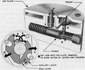
Figure 2 illustrates how the spin breaker is plugged into the bottom of the energizer. Drawings illustrating how the spin breaker operates ares shown in figure 3. The numbered arrows in the drawings denote the action and sequence of operations. The breaker con-sists of a metal body and cover plate; a stationary firing pin threaded into the side of the body; a plunger cup threaded into the top of the body; and levers, triggers, and a spring-loaded primer contained in the body. Operation of the spin breaker is as follows: The breaker is assembled with the interlocking levers held toward the axis by steel springs. They are so oriented that centrifugal force overcoming the resistance of the springs causes them to swing outward (1 and 2) thus unlocking the auxiliary trigger (3) and freeing the trigger. The trigger then rotates (4) from pressure of the compressed firing spring, allowing the primer in the primer carrier to be forced onto the firing pin by its compressed spring (5). The primer fires when it strikes the firing pin. The ampoule is broken when the plunger is forced through the bottom of the energizer by the explosion of the primer. The plunger is held in the retracted position, until the primer is fired, by a slight shoulder on the plunger that bears on the rim of the hole through the top of the plunger cup. The pressure from the exploding primer breaks down this shoulder and for-ces the plunger through the small hole (6). |
|
Figure 3. Simplified drawing showing operation of Spin Breaker Mk 1 Mod 0. |
|
|
|
The spin breaker operates with a rotational speed of between 1500 and 2100 r.p.m. |
|
In order to complete the electrcial circuit to the rear fitting, which contains the squib and safety switches, wires lead directly through the breaker body from connector clips at the top to connector pins at the bottom. When the spin breaker is used, the rear fit-ting then plugy into the spin breaker instead of directly into the bottom of the energizer. |
|
Dry Energizers. All current models of Navy VT fuzes contain wet-type reserve energi-zers. However, the first models, now obsolete, receivied their electrical energy from a dry energizer. The energizer was not connected to the electrical circuit until certain set-back switches were closed when the projectile was fired. Dry energizers deteriorated rapidly, having a shelf life of only about six months. |
|
The rear fitting consists of a plastic body housing the reed spin and mercury switches, and the squib. These parts are potted in wax for shock protection. The cover is a fabric-base phenolic disc attached by metal pins into the plastic body. A metal disc with a hole through the center for the squib to blow through is attached to the bottom by steel pins. Electrcial connections are from contact clips at the top to the squib and switches. A ground connection is made through one of the steel pins to the bottom disc. |
|
Squib. The squib or cannon primer consists of a small container of explosive with an em-bedded filament of fine wire attached to electric leads. When a surge of electrical cur-rent passes through it, the filament is heated to a very high temperature and ignites the explosive. |
|
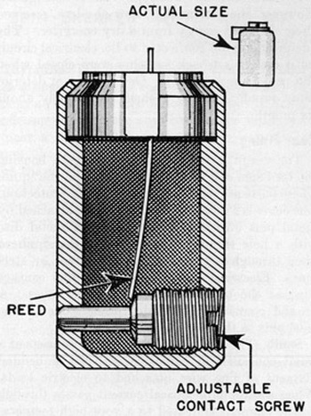
Reed Switch. The reed switch is electrically connected across the firing condenser to prevent the condenser from receiving a charge if the energizer becomes activated from accidental breakage of the electrolyte ampoule by dropping or rough handling. |
|
Figure 4 is a sectional drawing of the reed switch. The switch consists of a metal cup with an adjustable contact stud threaded through the lower side and a metal reed inser-ted through an insulator in the top of the cup. The reed serves as one terminal of the switch, and the adjustable contact stud serves as the other terminal. The spring action of the metal reed holds it in contact with the stud, making a closed circuit. The switch is mounted so that, when the projectile is fired, centrifugal force overcomes the restistan-ce of the reed, causing it to swing out from the contact stud, thus breaking the short circuit across the firing condenser immediately upon firing. |
|
|
|
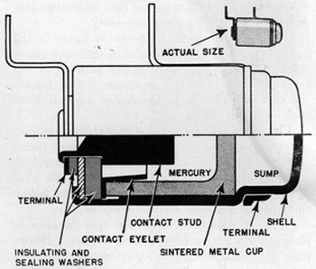
Mercury Switch. The mercury switch, when closed, completes a short circuit across the squib. |
|
It is a safety feature of the fuze designed to prevent a charge from passing through the squib in case the condenser accidentally received and released a charge. |
|
A drawing of the mercury switch is shown in figure 5. The principal parts are the metal body, a sintered metal cup, a metal contact stud, and a globule of mercury. The contact stud is extended through the top of the body into the inner chamber of the switch form-ed by the sintered metal cup. It is insulated from the body and makes one of the termi-nals of the switch. A brass eyelet which fits over the rim of the sintered cup makes pres-sure contact with the body and forms the other terminal of the switch. When assembled, the globule of mercury is in the sintered metal cup and in contact with the stud, thus acting to close the cirucit through the two terminals of the switch. |
|
|
|
The switch is mounted between the center and the outer periphery of the rear fitting, with the mercury toward the center and the sump farthest from the center. When the projectile is fired, centrifugal force acting on the mercury causes it to pass through the porous sintered metal cup into the outer chamber or sump, thus removing the short-cir-cuit it had imposed across the terminal of the squib. Continued pressure for a short time from centrifugal force is necessary to cause the mercury to pass through the sintered metal cup. |
|
Certain current fuzes, particularly some Mods of Mk 58, contain mercury switches which have a copper cup with a hole in the bottom covered with a paper disc in place of the sintered metal cup. Operation is a described above. The Fuzes Mk 47, Mk 53, and Mk 59 have two mercury switches wired in parallel across the terminals of the squib for additio-nal safety. |
|
Clock Works. Dry-energizer fuzes, now obsolete, contained a safety feature operated by a mechanical clockwork similar to the Time Fuze Mk 18. It ran for 0.4 to 0.6 seconds after leaving the gun, at which time it removed a mechanical gate from the canal bet-ween the auxiliary detonating fuze and the electrical squib. An electrical short circuit across the firing squib was broken only when the clockwork operated. |
|
The simpler-to-manufacture mercury switches supplant the clockwork in current fuzes; however they are not as positive or precise in their action. |
|
The auxiliary detonating fuzes used in VT fuzes are standard. A complete description of them can be found in OP 1212, Projectile Fuzes. |
|
The auxiliary fuze is assembled in the safe condition and is armed by centrifugal force. |
|
It is fired by the squib and in turn sets off the main charge of the projectile. |
|
The transmitter-receiver group and the amplifier, thyratron, and WSF group are assemb-led inside the fuze nose and secured by steel pins through the plastic base and rim of the shield can into a shoulder of the steel nose base ring. The press fit of these steel pins with the shield can completes the electrical ground to the fuze body and to the pro-jectile nose. Molten wax is poured into the nose to fill the void space. The wax solidifies and protects the units against the shock of handling and firing. |
|
The reserve energizer is plugged into the base of the amplifier, thyratron, and WSF group with a supporting washer interposed between them. A flat metal washer and rubber wa-ter-proofing gasket fit onto the flange of the supporting washer, to that when the body cylinder is screwed into the nose base ring the rubber gasket is compressed to form a waterproof seal. |
|
The rear fitting is plugged into the base of the energizer, with a rubber spacing washer inserted between them. In assembly, pressure is applied to the rear fitting, and the hold-ing ring is threaded into the body cylinder until it engages the base of the rear fitting. Pressure is then removed, and the holding ring is staked into position. The holding ring also completes the electrical ground from the base of the rear fitting to the fuze body. |
|
The auxiliary detonating fuze threads into the lower end of the body cylinder. Water-proofing is accomplsihed by means of a rubber waterproofing gasket sandwiched between two thin metal washers and held in compression between the fuze body cylinder and the lower part of the auxiliary detonating fuze by a threaded holding ring. |
|
|