|
|
| Fuzes for Rockets and Projector Charge |
| Chapter 9 |
| DECELERATION DISCRIMINATING BASE FUZES FOR FIN STABILIZED ROCKETS |
| Section A - Base Fuze Mk 162 Mod 0 (Pressure Arming, Deceleration Firing) |
| 1. General Data |
|
Used in: 11.75-inch Rocket Head Mk 2 Mod 1 (Common) |
|
Overall dimensions and weight of fuze: |
|
Length |
6.798 inches |
|
Diameter (maximum) |
3.200 inches |
|
Body threads |
2.75 inches - 14 NS-2 |
|
Weight |
4.90 lbs. approx. |
|
Applicable specification: OS 3856 |
|
General arrangement drawing: 562465 |
|
Sketch list of drawing & specs: 165244 |
|
Explosive components: |
|
A Percussion Primer Mk 101 (mercury fulminate primer mixture) located in the primer holder at the aft end of the detonator case. |
|
A 0.010 second black powder delay element, located in the delay pellet container in the detonator case. |
|
A Detonator Mk 33 Mod 1 (lead azide) located in the detonator case. |
|
Two detonator case lead-outs (tetryl) located in the detonator case. |
|
Two body lead-ins (tetryl) located in the body. |
|
Two body lead-outs (tetryl) located in the forward end of the body. |
|
A booster (approximately 28 grams tetryl) located in the magazine at the forward end of the body. |
| 2. Description |
|
General. Fuze Mk 162 is designed to detonate the round as it nears the end of its stable underground or underwater trajectory, or at any point within this trajectory after an impact, or after passing through a target backed by air. The fuzes fires the decelera-tion of the round has dropped below about 45 g. This corresponds to a distance of ap-proximately 200 feet of unobstructed underwater travel when the striking velocity of the round is 1300 feet per second. |
|
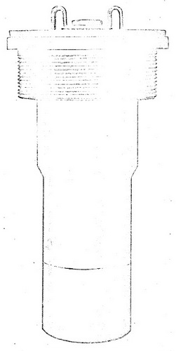
Figure 44 – Base Fuze Mk 162 Mod 0, External
View Full Size (approximately) |
 |
|
Use. The fuze is used in the 11.75-inch Common Fin stabilized Aircraft Rocket (Comp-lete Round) Mk 3 Mod 2 (see OP 1415). The round is prticularly effective against shipp-ing, earth covered pill boxes or bunkers, light and heavy fortifications, and very heavy vehicles and structures. |
|
Functioning mechanism. The fuze housing consists of a steel body, the forward end of which is closed by a booster magazine and the after end of which is closed by a gas chamber plug. |
|
The mechanism is contained in the fuze body, the after end of which contains a double chamber formed by the plug, the baffle cup, and the diaphragm. Gas from the rocket motor, utilized in arming the fuze, enters these chambers through the inlet valve. The diaphragm seals off the remainder of the fuze body cavity. Immediately beneath the diaphragm an aluminum arming sleeve is held in position by a shear wire. A pin through the arming sleeve engages the rotor, which is spring loaded by a torsion spring. The axial slots inside the rotor, which engage the arming sleeve pin, also engage the detonator plunger pin of the detonator plunger, and two pins pressed into the trigger block engage the rotor. A spring loaded firing pin is contained in the detonator plunger, to which is at-tached the detonator case containing the Primer Mk 101, the 0.010 second delay, Deto-nator Mk 33 Mod 1, and the detonator case lead-outs. |
|
In the unarmed position the detonator case lead-outs are so oriented that the deto-nator plunger assembly must be rotated 90° and also moved forward to line up the lead-outs with the body lead-ins. In the unarmed position the detonator plunger assembly is constrained from moving forward by the stop pins in the side of the fuze body. The loca-ting pin in the fuze body serves to orient the detonator plunger assembly and rotor cap assembly with respect to the fuze body. The spring loaded firing pin is held cocked by four lock balls, which are held in place by the trigger block. The trigger spring is com-pressed between the trigger latch and a shoulder on the trigger block. The trigger latch balls, bearing against the detonator plunger and a groove in the trigger latch, lock the trigger latch with respect to the trigger block. The closing plug serves to obturate and close the end of the fuze body cavity, and the magazine containing a tetryl booster pel-let covers the end of the fuze body. |
| 3. Functioning |
|
Arming. The arming schedule utilizes the following forces: 1. Forces due to motor gas pressure, 2. Spring force, 3. Creep force, 4. Impact force. The four principal steps of arming occur in the following manner: |
|
1. Fuze arming is initated by gas from the rocket motor, which enters the fuze through the inlet valve. Residue associated with burning of the propellant is filtered out by the inlet valve filter, which is made of Inconel wire mesh. Gas entering through the in-let orifice impinges on the inlet valve ball, forcing it forward off its seat to compress the inlet valve spring, and permit the gas to enter the first pressure chamber slowly. The gas is then allowed to flow more slowly into the second pressure chamber through a smaller orifice drilled in the baffle cup. When the pressure in the second chamber reaches a value of approximately 525 psi, the diaphragm collapses, forcing the arming sleeve for-ward and shearing the shear wire. The time at which the gas pressure in the second pressure chamber reaches the arming pressure value of 525 psi is dependet upon the pressure of the propellant gases in the rocket motor, which in turn depends upon initial propellant temperature. |
|
2. When the shear wire has been sheared, the arming sleeve and rotor are free so that the torsion spring can turn the rotor. The rotor, which also engages the detonator plunger pin and the trigger block (by means of the trigger block locating pins), rotates the detonator plunger trigger block assembly 90° until the rotor is stopped by the rotor-stop pin. The lead-outs in the detonator case are then lined up along the axis of the fuze with the lead-ins in the fuze body, but are still off-set with respect to them along the fuze axis. |
|
3. Slots in the end of the detonator plunger and stop pins in the body are also aligned by the rotation so that the detonator plunger trigger block assembly is free to move for-ward under the action of creep force until the trigger block rests against the shoulder in the fuze body. |
|
4. Friction of the firing-pin lock balls on the trigger block prevents the detonator plun-ger from moving farther forward until impact. Upon impact the detonator plunger moves forward until it is stopped by the shoulder in the fuze body. At this point the slots of the plunger engage the stop pins, the detonator case lead-out is aligned with the body lead-ins, and the plunger is locked by the detents. At the same time the trigger-latch lock balls fall in behind the shoulder on the detonator plunger, releasing the trigger latch, which was formerly locked with respect to the trigger block, which renders the trigger spring active. The trigger spring is then effectively compressed between the shoulder on the trigger block and the shoulder in the fuze body cavity and tends to force the trigger block toward the rear. |
|
Firing. As long as decceleration of the round is high, the inertia of the trigger block keeps the trigger spring compressed, but as soon as the deceleration is reduced below approximately 45 g, the spring overcomes friction forces and the inertia of the trigger block forces the trigger block to the rear off the firing-pin lock balls. The balls thus relea-sed move outward and release the spring-loaded firing pin. The firing pin initiates the primer, which initiates the black powder delay pellet (0.010 seconds) which in turn initia-tes the detonator and thus causes detonation of the explosive train of the fuze and the explosive filler in the head. |
|
Acceptance test data. Loaded fuzes from each lot are assembled in explosive loaded 5.0-inch sphere ogive rocket heads fitted with 5.0-inch Rocket Motors Mk 1 or Mk 2. The rockets are fired from a ground launcher into smooth water so that the angle of impact with the water is approximately 5°. Impact with the water is at a distance from the laun-cher that is greater than the maximum burning distance of the rocket motor. The water into which the rocket is fired is at least 30 feet deep at the point of impact. The round shall detonate high order after more than 50 feet of underwater travel as measured along the surface. Acceptance is based on a cumulative test plan designed to accept (95% of the time) lots in which 95% of the fuzes functon satisfactorily; lots poorer than 95% will be subject to rejection with lots 82% effective being rejected 90% of the time. |
|
Sensitivity limits. Very little information on the plate sensitivity of the Fuze Mk 162 has been obtained. |
| 4. Safety Features |
|
Detonator safety. Fuze Mk 162 is detonator safe. The detonator lead-outs and the booster lead-ins are out of alignment until after arming and impact. The lead-ous and lead-ins are both longitudinally and angularly out of alignment until after the first two arming steps have taken place. A large longitudinal displacement remains until after creep action is completed and lesser displacement exists unti after impact forces become ef-fective. |
|
During shipping and stowage. Sample fuzes from each production lot are subjected to rough handling tests which are considered to be more severe than conditions encoun-tered in normal stowage and shipping. Failure of the fuzes to pass the tests shall be cause for rejection of the lot. |
| 5. Disposal and Servicing (Maintenance) |
|
General. This fuze becomes quite sensitive after arming is completed and can be de-tonated reather easily. If an extremely light impact has resulted after gas pressure force, spring force and creep force have taken place, the fuze may be fired by an additional slight jar. A fuze which remains unfired after heavy impact is also very sensitive, inas-much as it may be expected that the firing pin has struck the detonator, and that sub-sequent friction between the firing pin and detonator, as incurred by rough handling, may fire the fuze. In any event, it is recommended that the fuze or fuzed round be disposed of by Explosive Ordnance Disposal Personnel in accordance with existing instructions. |
|
Disassembly. Disassembly of this fuze is not permitted except at authorized activ-ities when directed by the Bureau of Ordnance. |
| 6. Installation Instructions |
|
General. The fuze is shipped installed in the rocket head. No safety wire is provided, and no prepartions are required to ready the fuze for use. The shipping cap, protecting the rocket head base, protects the fuze also. This cap should remain in place until as-sembly of the round begins and should be replaced on disassambly. Before assembling the rocket head to the rocket motor be certain that the fuze is present and properly instal-led, and that the assembly is properly gas checked. |
| 7. Packing and Marking. |
|
Packing. The fuze is shipped assembled into the base of the rocket head. |
|
Marking. The fuze is marked or stamped with the mark, mod, and lot number, the ma-nufacturer's intials or symbol, the initials or symbol of the loading facility, the month and year of loading, the anchor stamp, and the inspector's initials. |
|
|