|
|
| Fuzes for Rockets and Projector Charge |
| Chapter 8 |
| BASE FUZES FOR FIN STABILIZED AIRCRAFT ROCKETS |
| Section C - Nose Fuze Mk 163 Mods 0 and 1 (Pressure Arming, Impact Firing) |
| 1. General Data |
|
Used in: 11.75-inch Rocket Head Mk 1 Mod 1 and Mk 2 Mod 0 (Common) |
|
Overall dimensions and weight of fuze: |
|
Length |
6.49 inches |
|
Diameter (maximum) |
3.2 inches |
|
Body threads |
2.75 inches - 14 NS-2 |
|
Weight |
3.4 lbs. approx. |
|
Applicable specification: OS 3699 |
|
General arrangement drawing: 561459 |
|
Sketch list of drawing & specs: |
|
165238 (Mod 0) |
|
165442 (Mod 1) |
|
Explosive components: |
|
Delay detonator assembly (adapted from the delay detonator assembly of Fuze Mk 157). The assembly consists of a mercury fulimate Percussion Primer Mk 106, an expan-sion space, the 0.020 second black powder delay element and the Relay Detonator Mk 42 Mod 0 (lead azide) assembled in a single case closed by a crimp and contained in shut-ter. |
|
Booster lead-in charge (tetryl). |
|
Booster charge (approximately 12 grams tetryl) contained in magazine. |
| 2. Description |
|
General. The Base Fuze Mk 163 Mod 0 and 1 was developed by modifiying Fuze Mk 157 Mod 2. It has essentially the same functioning mechansim with the following modifi-cations included to improve the performance on heavy oblique impacts: |
|
1. A setback block and setback spring is included in the lead-in and shutter lock as-sembly which takes the place of the lead-in disc in Fuze Mk 157. The setback block with the shutter lock pin attached provides a more positive setback operated, arming delay. During acceleration of the rocket, the setback spring is compressed by the inertia of the setback block, and the shutter-lock pin engages the detent hole in the shutter. When acceleration is over, the shutter-lock pin is withdrawn, releasing the shutter, which in turn is then rotated into the armed position by the shutter spring. |
|
2. The possible gap of 0.058 inches between the detonator and lead-in is reduced to 0.025 inches, for more positive assurance of high order functioning. |
|
3. The shutter is hinged at both ends of the hinge-pin, and another detent is added. The use of two detents reduce the probability of the shutter being knocked out of posi-tion by an oblique impact. The shutter spring functions only as a torsion spring and not as a compression and torsion spring as in Fuze Mk 157. |
|
The overall length of Fuze Mk 163 is approximately 0.33 inches greater than of Fuze Mk 157 Mod 2. The additional length requires a deeper fuze cavity in the head filler. |
|
Fuze Mk 163 Mod 0 has arming constant the same as the Fuze Mk 157 Mod 2. When the inlet screen was replaced by a filter formed by compressing Inconel wire mesh and the inlet orifice and shear wire were replaced by those from the Fuze Mk 159 Mod 1, the fuze was designated the Mk 163 Mod 1. These changes increased the arming pressure (310 to 375 psi) and partial arming delay. |
|
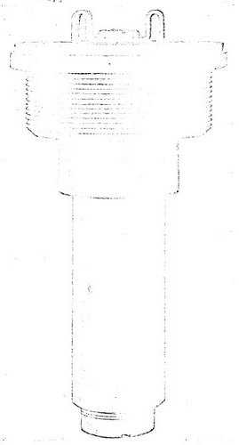
Figure 38 – Base Fuze Mk 163, External
View Full Size (approximately) |
 |
|
Use. Fuze Mk 163 Mods 0 and 1 is used in the 11.75-inch Common Fin Stabilized Air-craft Rockets (Complete Rounds) Mks 3 Mod 0 and Mk 3 Mod 1 (see OP 1415). The 11.75-inch Rocket Head Mk 2 Mod 0 contains three Mk 163 Fuzes. The complete round is used against shipping and heavy fortifications. Fuze Mk 163 will fire with 0.020 second delay upon impact with a suitable target. |
|
Functioning mechanism. The functioing mechanism in Fuze Mk 163 is the same as in Fuze Mk 157 except as noted in paragraph 1, General. |
|
Figure 39 – Base Fuze Mk 163 Mod 1, Partial Cross Section View Showing the Operation of the Setback Block when Rocket Accelerating. |
|
|
|
Figure 40 – Base Fuze Mk
163 Mod 1, Partial Cross Section View, |
|
|
| 3. Functioning |
|
Arming. Arming of Fuze Mk 163 is identical with Fuze Mk 157 except that the shutter is kept from rotating into the armed position by the shutter locking assembly until acce-leration has ceased. |
|
Firing. Firing upon impact is identical is essentially the same as with Fuze Mk 157. |
|
Acceptance test data. Those fuzes selected for functional tests are assembled in explosive loaded 5.0-inch Rocket Heads Mk 6 Mod 1 fitted with a flat nose shipping plug and 5.0-inch Rocket Motors Mk 2. The rounds are fired from a ground launcher at an angle of elevation of approximately 15 degrees for water impact. Acceptance is based on a cumulative test plan designed to accept (95% of the time) lots in which 92% of the fuzes function satisfactory; lots poorer than 92% will be subject to rejection with lots 78% effective being rejected 90% of the time. |
| 4. Safety Features |
|
Same as Fuze Mk 157. |
| 5. Disposal and Servicing (Maintenance) |
|
Same as Fuze Mk 157. |
| 6. Installation Instructions |
|
Same as Fuze Mk 157. |
| 7. Packing and Marking. |
|
Same as Fuze Mk 157. |
|
|

