|
|
| Fuzes for Rockets and Projector Charge |
| Chapter 8 |
| BASE FUZES FOR FIN STABILIZED AIRCRAFT ROCKETS |
| Section A - Nose Fuze Mk 157 Mods 0, 1 and 2 (Pressure Arming, Impact Firing) |
| 1. General Data |
|
Used in: |
|
Mk 157 Mod 0 in 5.0-inch Rocket Heads Mk 1 and Mk 1 Mod 1 (General Purpose) |
|
Mk 157 Mod 1 in 11.75-inch Rocket Head Mk 1 (Common) |
|
Mk 157 Mod 2 in 11.75-inch Rocket Heads Mk 1 Mod 0 and Mk 2 (Common) |
|
Overall dimensions and weight of fuze: |
|
Length: |
|
|
6.170 inches (Mod 0 & 1) |
|
|
6.196 inches (Mod 2) |
|
|
Diameter (maximum): |
|
|
2.938 inches (Mod 0 & 1) |
|
|
3.200 inches (Mod 2) |
|
|
Body threads |
2.750 inches – 14 NS-2 |
|
Weight: |
|
|
3.40 lbs. approx. (Mod 0 & 1) |
|
|
3.50 lbs. approx. (Mod 2) |
|
|
Applicable specification: OS 3535 |
|
General arrangement drawing: |
|
438015 (Mod 0) |
|
439629 (Mod 1) |
|
439630 (Mod 2) |
|
Sketch list of drawing & specs: |
|
109475 (Mod 0) |
|
165111 (Mod 1) |
|
165123 (Mod 2) |
|
Explosive components: |
|
Delay detonator assembly (adapted from the delay detonator assembly of Fuze Mk 145.) The assembly consists of a mercury fulminate Percussion Primer Mk 106, an expan-sion space, the 0.020 second black powder delay element and the lead azide Relay Deto-nator Mk 31 Mod 0 all in a single case closed by a crimp and located in the shutter. |
|
Booster lead-in charge (tetryl) loacted in lead-in disc. |
|
Booster charge (approximately 12 grams tetryl) located in magazine. |
| 2. Description |
|
General. Fuze Mk 146, which is now obsolete, was originally developed for use in the 5.0-inch Aircraft Rockets1. Service use of the 5.0-inch Aircraft Rocket soon indicated that a longer delay than that inherent in Fuze Mk 146 was necessary in order to obtain the desired penetration of targets before detonation. For this reason Fuze Mk 146 was modified to incorporate a 0.020 second delay detonator and designated Fuze Mk 157 Mod 0. Since the delay detonator has a percussion primer, the stab type firing pin of Fuze Mk 146 is replaced by a firing pin with a rounded point. |
|
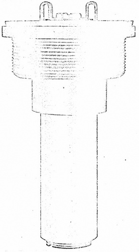
Fuze Mk 157 Mod 1 differs from Fuze Mk 157 Mod 0 in that the head and body are manufactured from pearlite manganese steel for additional strength, also the 2.75-inch diameter threads on the fuze head extend the full length of the head. Fuze Mk 157 Mod 2 is identical with the Fuze Mk 157 Mod 1 except that it provides for external gas checking by means of the copper and lead gaskets. |
|
Figure 34 – Base Fuze Mk 157 Mod 2, External
View Full Size (approximately) |
 |
|
Use. Fuze Mk 157 Mod 0 is used in the 5.0-inch General Purpose Fin Stabilized Aircraft Rockets (Complete Rounds) Mk 1 Mod 2, Mk 1 Mod 4, Mk 1 Mod 5, and Mk 4 Mod 0 (see OP 1415). Rockets employing these fuzes are used against shipping, light fortifications, such as pill boxes, and personnel. Fuze Mk 157 Mod 1 and Mod 2 are used in the 11.75-inch Common Fin Stabilized Aircraft Rocket (Complete Rounds) Mk 3 Mod 0 and Mk 3 Mod 1 (see OP 1415). The 11.75-inch Aircraft Rocket utilized Fuzes Mk 157 Mod 1 and Mod 2 are used against shipping and heavy fortifications. Fuze Mk 157 and Mods will fire with a 0.020 second delay upon impact with suitable targets. |
|
Functioning mechanism. Two parts called the head and body house the fuze me-chansim. The head contains a gas chamber formed by the plug and the diaphragm. Gases from the rocket motor are permitted to flow slowly into the gas chamber through an ori-fice in the inlet screw, after first being filtered by the inlet screen. Immediately beneath the diaphragm and in the body, an aluminum arming plunger is held in position by a shear wire. |
|
In the unarmed position the arming plunger holds a locking ball in such a position as to lock the firing pin body and firing pin in the forward position, compressing the firing pin spring. While in the forward position, the firing pin extends through the firing pin guide and into a cavity in the shutter. This cavity in the shutter is so positioned that when en-gaged by the firing pin the delay detonator assembly is out of alignment with the tetryl booster lead-in and the firing pin. Rotation of the shutter to bring the explosive elements in line, when released by withdrawal of the firing pin, is accomplished by means of the shutter spring. Since the firing pin must not puncture the cover of the percussion primer, the firing pin is made so as to shoulder against the face of the detonator case to that the point will indent the proper distance into the primer. To avoid crushing of the deto-nator case by the weight of both the firing pin and firing pin body on heavy impacts, the firing pin is secured in the firing pin body by means of a shear wire. On heavy impacts the inertia of the firing pin body shears the wire holding the firing pin, and the two parts telescope. |
|
A lead-in disc containing a tetryl lead-in charge is inserted in the fuze body between the shutter and the tetryl magazine charge. |
| 3. Functioning |
|
Arming. The fuze head screws into an adapter fixed in the base of the rocket head. The gasket and the lunting on the threads of Fuze Mk 157 Mods 0 and 1 or the projectile type gas check used with Fuze Mk 157 Mod 2, are provided to make a gas tight seal in the adapter between the rocket motor and the interior of the rocket head. The rear end of the fuze (the exterior surface of the plug) is exposed to the front end of the rocket motor. The fuze arms in two stages: |
|
1. Gases from the rocket motor, at pressures ranging from 300 to 1600 psi for the 3.25-inch Motor Mk 7 and 800 to 2350 psi for the 11.75-inch Motors Mk 1, enter the pressure chamber in the head of the fuze through a small orifice in the inlet screw. De-bris from the rocket motor is filtered out by the inlet screen. When pressure in the cham-ber has reached a value of 275 to 325 psi, which is delayed by the small orifice until approximately half the propellant burning time is consumed, the diaphragm collapses, forcing the arming plunger down and shearing the shear wire which holds the arming plunger in place. Movement of the arming plunger releases the locking ball, which, in the unarmed condition, locks the firing pin body in place, and allows the latter to move to-ward the rear under the force of the firing pin spring and the inertia of the firing pin body due to acceleration. The firing pin, attached to the firing pin body, is thus withdrawn from the detonator shutter, which is normally locks in the safe position. |
|
2. When the rocket accelerates, the inertia of the shutter forces it back against the firing pin guide, compressing the shutter spring and engaging the shutter locking pin in a hole in the firing pin guide. About midway during acceleration, the firing pin is withdrawn from the shutter; but the shutter, held by the shutter locking pin, remains locked in the safe position. |
|
When acceleration is over, the shutter spring forces the shutter forward against the lead-in disc disengaging the shutter locking pin from the hole in the firing pin guide. The shutter spring then swings the shutter into the armed position (detonator assembly in line with firing pin and lead-in) where it is locked by the detent. (See paragraph 4 for arming distance of Fuze Mk 157 and Mods.) |
|
Firing. The fuze fires upon impact with any material offering sufficient resistance. Under the force of impact the inertia of the firing pin body drives the firing pin forward, striking and initiating the percussion primer in the detonating assembly. The percussion primer initiates the explosive train in the detonator assembly (i.e., black powder delay and relay detonator). The detonator assembly in turn initiates the tetryl lead-in and te-tryl booster, which detonates the main explosive charge of the rocket head, either di-rectly or through the auxiliary booster. |
|
Acceptance test data. Sample fuzes selected at random from each production lot are subjected to routine safety tests and ballistic tests when fired in rocket ammunition in accordance with the following procedures: |
|
1. Completely live-loaded from each lot shell be assembled in explosive loaded 5.0-inch Rocket Heads Mk 1 fitted with flat nose shipping plugs and 3.25-inch Rocket Motors Mk 7 and shall be fired at angles of elevation from 8 to 11 degrees for noticeable delayed action high order functioning after water impact. Satisfactory performance for this test shall be considered 90% delayed action high order functioning. |
|
2. Completely live-loaded fuzes from each of the first twenty lots and from the 25th, 30th, 35th, etc., lots thereafter shall be assembled in explosive loaded 5.0-inch Rocket Heads Mk 1 fitted with pointed steel nose plugs and 3.25-inch Rocket Motors Mk 7 and fired for impact against ¼-inch, 3/8-inch, 5/8-inch, and 1-inch STS plates at the discre-tion of the Naval Proving Ground for the purpose of adding to the present knowledge of the plate performance of this fuze. Performance of the fuzes in this test shall be report-ed but shall not be an essential criterion in determining the acceptance of the lot. |
|
Sensitivity limits. Because the percussion primer is less sensitive than the stab type sensitive primer, Fuze Mk 157 is less sensitive than Fuze Mk 146. Tests of Fuze Mk 157 against plate indicated that functioning on mild steel plate targets less than ½ inch in thickness is unreliable. |
| 4. Safety Features |
|
Detonator safety. Fuze Mk 157 Mods 0, 1, or 2 is detonator safe. In the unarmed position, the detonator assembly is out of alignment with the explosive train. Should the detonator assembly function prematurely, the force of the detonation will be dissipated upward through a hole in the firing pin guide and away from the balance of the explosive train. Because of the delay in admission of gas from the rocket motor to the pressure chamber, the first stage in arming does not occur until approximately one-quarter to one-half of the rocket propellant burning time is completed. Because of this delay, if the rocket motor blows up before it leaves the launcher, the fuze should not arm. Arming is not completed until after acceleration has dropped to a value corresponding to nine g. The burning distance, and therefore the arming distance, will vary with the temperature. On the average, arming is completed about 0.1 second after the end of burning. Approxi-mate arming distances for Fuze Mk 157 and Mods in the 5.0-inch and the 11.75-inch air-craft rockets are: |
| ° | ° | ° | |
| Temperature |
0 F. |
70 F. |
135 F. |
| 5.0-in. A R (3.25-in. Mk 7 Motor) | 575 ft. | 350 ft. | 250 ft. |
|
11.75-in. AR (11.75-in. Mk 1 Motor) |
670 ft. |
450 ft. |
350 ft. |
|
During shipping and stowage. Sample fuzes from each production lot are subjected to rough handling tests which are considered more severe than conditions encountered during normal shipment and stowage. Failure to pass these tests shall be cause for re-jection of the lot. |
| 5. Disposal and Servicing (Maintenance) |
|
General. From an examination of the exterior of the fuze, it is impossible to tell whether or not the fuze is armed. If, for any reason, it is thought that the fuze may be armed, it should be treated as an armed and sensitive fuze. No attempt should be made to remove the fuze from the rocket body. The complete fuze round should be disposed of by gently lowering it, tail first, into deep water, or by Explosive Ordnance Disposal Per-sonnel in accordance with existing instructions. |
|
Disassembly. Disassembly is not permitted except at authorized activities when di-rected by the Bureau of Ordnance. |
| 6. Installation Instructions |
|
The fuze is shipped installed in the base of the rocket head. A safety wire is not ne-cessary and no preparations are required to ready the fuze for use. A shipping plug or shipping cap protects the exposed end of the fuze and the outside threads of the head. The shipping plug or the shipping cap should be kept in place until the round is assemb-led and should be promptly replaced if the round is disassembled. Before assembling the rocket head to the rocket motor be certain that the fuze is in place in the base adapter, and that the gas check gaskets are properly installed where required. |
| 7. Packing and Marking. |
|
Packing. Fuzes will be shipped assembled in the rocket heads and protected by a shipping plug which screws into the base adapter or by a shipping cap which screws over the outside threads of the head. |
|
Marking. The fuze is marked or stamped with the mark, mod, and lot number; the date of loading; the manufacturer's initiale or symbol; and the initials or symbol of the loading facility; the month and year of loading; the anchor stamp; and the inspector's initials. |
|
|