|
|
| Fuzes for Rockets and Projector Charge |
| Chapter 7 |
| NOSE FUZES FOR 7.2-INCH ANTI-SUBMARINE ROCKETS AND 7.2-INCH PROJECTOR CHARGE AMMUNITION |
| Section A - Nose Fuze Mk 156 Mod 0 (Water Travel Arming, Impact Firing) |
| 1. General Data |
|
Used in: |
|
7.2-inch Rocket Head Mk 5 (High Capacity) |
|
7.2-inch Projector Charge Head Mk 4 (High Capacity) |
|
Overall dimensions and weight of fuze: |
|
Length |
7.385 inches |
|
Diameter (maximum) |
3.125 inches |
|
Body threads |
2.00 inches - 12 NS-2 |
|
Weight |
2.8 lbs. approx. |
|
Applicable specification: OS 3418 |
|
General arrangement drawing: 438552 |
|
Sketch list of drawing & specs: 109482 |
|
Explosive components: |
|
Detonator Mk 23 Mod 0 (lead azide priming mixture and lead azide) contained in shut-ter assembly. |
|
Booster lead-in charge (tetryl) contained in lead-in disc. |
|
Booster charge (approximately 9 grams tetryl) contained in magazine. |
| 2. Description |
|
General. The Rocket Nose Fuze Mk 156 Mod 0 is very similar to its predecessor, Fuze Mk 131, except that it incorporates numerous changes found desirable after extensive tests. It is a very sensitive contact fuze which depends on setback in air and passage through water to arm. After arming the fuze functons instantaneously upon impact with any underwater obstruction and the mechanism is so constructed that either normal or oblique impact will cause functioning. Arming is accomplished by four to eight vane revo-lutions which occur within 15 to 21 feet of water travel. |
|
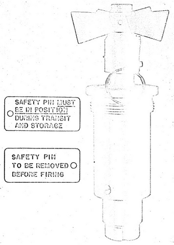
Figure 31 – Nose Fuze Mk 156 and Mk 158,
External View, Full Size (approximately) |
 |
|
Use. Fuze Mk 156 Mod 0 is used in 7.2-inch High Capacity Surface Fin Stabilized Rockets (Complete Rounds) Mk 1 Mod 0 and Mk 1 Mod 1 (see OP 1415). The fuze is used exlusively against submarines and its aerodynamic characteristics limit its use to low ve-locity rounds. |
|
Functioning mechanism. The fuze housing consists of the fuze body, plug, and ma-gazine. The steel fuze body is machined to accommodate the lead-in disc, shutter as-sembly, and firing assembly. The forward end of the body is provided with external threads to engage the rocket head when the fuze is installed and internal threads to en-gage the plug. |
|
The steel plug is machined out and provided with internal threads to accommodate the arming screw. The aft end has external threads to engage the fuze body. |
|
The arming vane and arming vane hub are secured to the arming screw by a set screw. A setback collar is fitted over the plug nock and the arming vane hub which pro-vides a means of locking the arming vane until the rocket is fired. |
|
Locking pins in the arming vane hub and the plug, respectively, fit into a slot in the setback collar, positively locking the arming vane until the setback force causes the set-back collar to move backward on the plug. The setback collar is maintained in the for-ward position by the tension of the flat spring plate on the locking pins. |
|
An internal radial shear wire (inserted into matching holes in the arming screw and plug) prevents the air stream from turning the arming vane and arming the fuze during air travel. |
|
The firing assembly located in the body cavity, consists of the firing pin, the firing pin spring, the firing pin sleeve, the sleeve spring, the firing pin head, the weight, the retain-ing ring, and three balls. When the fuze is unarmed, the firing assembly is held in place by the arming screw and the firing pin rests in a well in the shutter retaining it in the un-armed position. With the firing assembly in the unarmed position, the firing pin is held in the cocked position, with the firing pin spring compressed, by three steel balls which are wedged between the firing pin head and the angular lip on the weight. The force of the firing pin spring under compression keeps the wedging action constant until the arming screw is withdrawn and impact forces the weight forward. |
|
The shutter is located immediately below that portion of the body which forms the firing pin guide. The shutter contains a spring loaded detent which locks it in the armed position. A torsion spring rotates the shutter into the armed position as soon as the firing pin is withdrawn from the shutter cavity. |
|
A lead-in disc containing a tetryl lead-in is inserted immediately below the shutter and the booster magazine containing a tetryl charge is screwed into the base of the fuze body. |
|
Figure
32 – Nose Fuze Mk 156 Mod 0 or Mk 158 Mod 0, Cross Section View, |
|
|
|
Figure 33 – Nose Fuze Mk 156
Mod 0 or Mk 158 Mod 0, Cross Section View, |
|
|
| 3. Functioning |
|
Arming. When the rocket with the fuze installed is fired from a launcher, setback for-ces at the instant of firing cause the setback collar to move backward and unlock the arming vane. The setback collar is prevented from moving forward again by the flat spring plate dropping down behind the locking pin in the plug. The internal radial shear wire between the vane hub and the plug prevent the air stream from turning the arming vane and arming the fuze during air travel. Upon impact with the surface of the water, the impact force causes the arming vane to rotate and shear the radial shear wire. Con-tiniuing rotation of the arming vane withdraws the arming screw and arms the fuze. The firing assembly moves with the arming screw under force of the sleeve spring until the firing pin sleeve meets the retaining ring. At the end of travel of the arming screw, the rubber sealing washer is jammed between the plug and the sealing collar, which is faste-ned to the arming screw by a cotter pin, there by sealing the fuze. |
|
As the firing assembly moves forward, the firing pin is withdrawn from the shutter ca-vity, releasing the shutter. The shutter spring rotates the shutter against the stop pin thus aligning the detonator in the shutter with the booster lead-in and with the firing pin. Two pairs of sleeve stops are pushed inward by the stop springs, one pair just before the firing pin releases the shutter, and the other pair just after the release. |
|
Firing. Firing is initiated (after the fuze has armed) by impact with any underwater obstruction offering sufficient resistance. Inertia causes the weight to move forward on normal impact or laterally on oblique impact, thereby allowing the three balls to move out and release the spring driven firing pin. The firing pin pierces and initiates the detonator which in turn initiates the lead-in and magazine charge and in turn the main explosive charge in the rocket head. |
|
Acceptance test data. Sample fuzes selected at random from each production lot are subjected to routine safety tests and ballistic tests when fired in rocket ammunition in accordance with the following procedure: |
|
1. Premature and Blade Test – Fuzes from each lot, completely loaded except for inert boosters, shall be assembled in 7.2-inch rockets. Half the rounds shall be launched at a striking velocity of 170 feet per second, and the balance at 190 feet per second, into 25 feet of water with the round attached to a line and spring arrangement. All the rounds shall be recovered by suitable nets before striking the bottom, and the fuzes shall be fully armed but not fired. Failure of any fuze to pass this test shall cause rejection of the lot. All of the fuzes used in this test shall be saved for the "Functioning Test" described in the next paragraph. |
|
2. Functioning Test – The fuzes used for the Premature and Blade Test shall be re-used in this test. The fuzes shall be assembled in 7.2-inch rockets (inert loaded to a weight of 65 pounds). The rockets shall be fitted with a retarding disc suitable to limit the underwater terminal velocity to 22 or 23 feet per second. The fuzes shall be prearm-ed by the Premature and Blade Test and dropped in water so that the terminal velocity is reached, and the nose of the fuze strikes No. 1 grade fir battens 1¼-inch x 3-inch laid flat with ¾-inch spaces between them on supports two feet apart. The slats shall be firmly fastened to supports which have a solid foundation. Ninety percent high oder func-tioning shall be considered satisfactory. |
|
Sensitivity limits. Fuze Mk 156 Mod 0 is equipped with a spring driven firing pin and will fire after arming upon impact with any underwater obstruction which creates suffici-ent deceleration to move the weight either forward on a normal impact or laterally on an oblique impact. Obstructions such as the steel surface or the wooden deck gratings of a submarine will consistently function the fuze. |
| 4. Safety Features |
|
Detonator safety. The fuze is detonator safe. The firing pin, protruding into the shutter cavity when the fuze is unarmed, holds the detonator out of alignment with the tetryl lead-in and booster charge. Premature functioning of the detonator while the fuze is unarmed will not detonate the booster lead-in and booster. |
|
During shipping and stowage. Sample fuzes from production lots are subjected to rough handling tests which are considered to be more severe than conditions encounter-ed in normal stowage and handling. Failure to pass the tests is cause for rejection of the lot. The setback collar prevents rotation of the water arming vane until the setback for-ces, acting on the collar at the instant of firing, cause it to move backward on the plug, thereby freeing the arming vane (except for the radial shear wire). A safety pin, which is inserted through the steback collar, a plug, and an arming screw, prevent movement of the setback collar during transportation and stowage. The radial shear wire, in addition to its primary function of preventing the vane from turning during the air travel after be-ing fired, also provides a safety feature. The arming vane will not be rotated, even if the setback collar has moved back on the plug, unless considerable force is applied to the vane. |
| 5. Disposal and Servicing (Maintenance) |
|
General. This fuze is very dangerous to handle when armed, therefore, disposal and handling under such circumstances is considered most hazardous. Accordingly, the pre-cautions below are to be rigidly followed: |
|
1. The safety pin must be in place through the setback collar at all times and not removed until just prior to the firing of the round. In case the salvo is not fired immediately after removal of the safety pin, the safety pin must be reinserted. |
|
2. The setback collar of this fuze must not be manually retracted under any operating conditions. |
|
Disassembly. Disassembly of this fuze is not permitted except at authorized activi-ties when directed by the Bureau of Ordnance. |
| 6. Installation Instructions |
|
To install the fuze in the rocket: |
|
1. Remove the steel fuze cap and the shipping plug from the nose of the charge. |
|
2. Remove the cardboard shipping spacer from the fuze seat liner. |
|
3. Make sure that the auxiliary booster shipped with the charge is properly located. |
|
4. Remove the fuze from its sealed container and make sure that the safety pin is se-curely in place. |
|
5. Screw the fuze into the nose of the rocket head, making sure that the gasket bet-ween the fuze and the fuze seat liner is in place. Tighten with a spanner wrench so that the joint so that the joint is watertight. (Note: The pins of the spanner wrench used (BuOrd Sk 119862) shall be fitted into the holes in the fuze body and not into the holes in the plug; that is, they shall be fitted into the outer pair of holes.) Do not grasp the fuze by the arming vane or use a pipe wrench or any other tool on the plug, set-back collar, or arming wire vane when installing the fuze in a rocket. It this pre-caution is not followed, the plug may be unscrewed and/or the arming vane turned, thereby arming the fuze. There is on record a serious accident caused by the use of im-proper tools. |
|
6. Replace the fuze cap over the fuze, for protection against the weather and safety in handling. This completes the installation for ready ammunition. |
|
7. After the rockets are placed on the launcher, and just prior to firing remove the fuze cap and the safety pin through the setback collar. Save the safety pins, to that they can be reinserted into the setback collars in case the salvo is not fired. Daily in-spections should be made of all fuzed rounds to make sure that the fuze is in a safe con-dition and that the safety pin is present. |
|
It is important that the following points be checked: |
|
1. That the correct fuze is installed in the proper rocket and used with the proper launcher. |
|
2. That the fuze cap and safety pin are removed just prior to firing of the round. |
|
3. That the setback collar is in the forward position, with the spring plate over the vane locking pins after installation. |
|
4. Daily inspections should be made of any fuzed rounds which are on the launcher rails to see that the safety pins are correctly installed and the fuzes have not been part-ially of fully armed by some accidental means. |
|
Removal from round. Should it become necessary, the fuze may be removed from the rocket head and returned to its container. However, first be sure that the safety pin through the setback collar is in place. The fuze should be removed from the round if for any reason the round is to be taken below decks. Use a spanner wrench (BuOrd Sk 119862) to remove the fuze. (Note: The spanner wrench should fit the holes in the fuze body and not the holes in the plug; that is, it should fit the outer pair of holes.) Do not grasp the fuze by the arming vane or use a pipe wrench or any other tool on the plug, setback collar, or arming wire vane when installing the fuze in a rocket. If this precaution is not followed, the plug may be unscrewed and/or the arming vane turn-ed, thereby arming the fuze. |
| 7. Packing and Marking. |
|
Packing. One fuze is packed in a sealed cylindrical metal container 3 7/16 inches no-minal diameter, and 8.0 inches nominal length. The weight of the fuze and detonator is 3.36 pounds. A scored metal tear strip facilities opening of the container. The container is stamped with the mark and mod of the fuze. |
|
Twenty-four fuzes, packed in the fuze containers, are packed in a wooden shipping box 25.5 inches by 16.5 inches by 9.7 inches representing 2.3 cu. ft. The weight of the box and fuzes is approximately 108 pounds. |
|
Marking. The fuze body is marked or stamped with the mark, mod, and lot numbers, the manufacturer's initials or symbol, the initials or symbol of the loading facility, the month and year of loading, the anchor stamp, and the inspector's initials. |
|
|

