|
|
| DEPTH CHARGES MARK 6 and MARK 7 |
| PART II |
| CHAPTER V - INSPECTION AND TESTING GENERAL INSTRUCTIONS |
|
TESTING BOOSTER EXTENDERS |
|
9. The standard functional test procedure for Booster Extender Mechanism using the Mark 2 Mod. 1 test set is as follows: |
|
(a) Place the extender mechanism in the holder of the testing set. Pull off the safety fork. The hook on the extender testing tool may be used to pull off the plain type safety fork. When the safety fork is removed the extender spindle should move in approximately one quarter of an inch and open a passage for the entrance of air around the end of the spindle. |
|
NOTE: Failure of the Mark 6 extender mechanism to meet this requirement should be rarely encountered. However, the Mark 6 Mod. 1 extender mechansim is equipped with a seal housed in the spindle bushing and failure of the spindle to move inward due to tightness of this seal will sometimes be encountered. See instructions noted in paragraph 19 (a) of Chapter IV. |
|
(b) Place hook of extender testing tool in the hole at the end of the spindle and pull the spindle out. Secure the extender stop on the end of the spindle and allow the spindle to slip back into the hole in the spindle bushing carrying the extender stop with it. See that the extender stop is centrally located with respect to the spindle so that this can take place. |
|
NOTE: It will be necessary to drill a one eight inch diameter hole in the extender stop for use with the Mark 6 Mod. 1 extender mechanism. Such a hole is necessary to insure the passage of air by the seal around the spindle. This hole should be cen-trally located on the flanged head of the extender stop and terminate in the cavity provided for the end of the spindle. |
|
(c) Make up the test fixture with rubber washer, cover and clamping piece, as when tes-ting a pistol. |
|
(d) Pumping air into the system until the booster spindle extends to the full travel per-mitted by the extender stop. This should occur at a, pressure of 4 to 10 pounds per square inch to be satisfactory. If it does not, tag the mechanism to indicate the fault and set it aside for reconditioning. |
|
(e) If the mechanism operates within the limits specified, continue to pump air into the system until a pressure of 30 pounds per square inch is obtained. If the indicated pres-sure on the gauge does not drop more than 5 pounds in one minute, the mechanism is satisfactory. If the test indicates that the mechanism leaks, tag it to indicate this fact and set it aside for reconditioning at an overhaul station. |
|
NOTE: When leaks are observed while making tests, be sure the leak is not in the testing set. |
|
Check all extender mechanisms to insure that they are fitted with bellows retainer. |
|
|
|
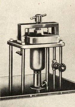
PISTOL TESTING FIXTURE |
|
(f) The standard functional tests of booster extender noted in this paragraph may be performed with the use of pistol testing fixture, the operation of which is described in paragraph (7) of this chapter. |
|
|