|
|
| DEPTH CHARGES MARK 6 and MARK 7 |
| PART I |
| CHAPTER II - PARTS |
| MARK 6 BOOSTER EXTENDERS |
|
|
|
Blue indicates exterior - Red indicates interior |
|
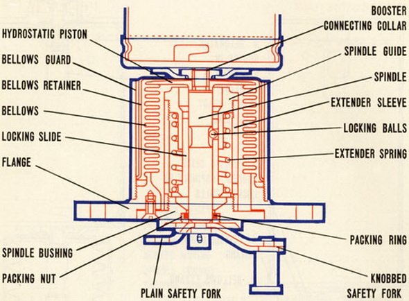
39. The principal parts of the Mark 6 booster-extender are: |
|
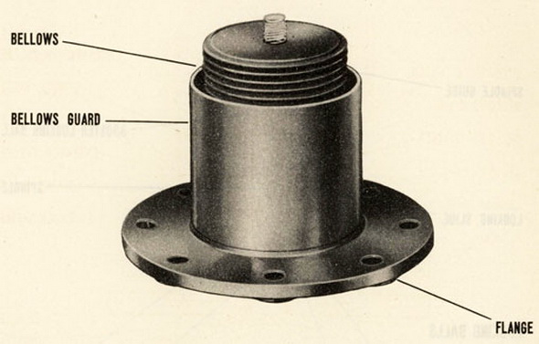
a. flange with which the mechanism is secured in the central tube of a depth charge case |
|
a metall bellows which forms an expansive watertight container for the operation parts of the booster-extender |
|
a bellows guard to protecht the bellows |
|
a piston |
|
a spindle and spindle guide |
|
a locking slide. |
|
Since the mechanism may be used with a Mark 6 Mod. 1 pistol the original design has been modified to include a bellows retainer. Any mechanisms not so equipped should be modified in accordance with Ordalt No. 1505. |
|
|
|
|
|
Blue indicates exterior - Red indicates interior |
|
40. The outer end of the bellows secured to the inner side of the flange, while the piston is fastened to the inner end of the bellows. A cupped shaped retainer is placed over the piston and bellows. A collar for attaching a booster can to the mechanism is mounted on the inner end of the mechanism and secures the bellows retainer in place. |
|
|
|
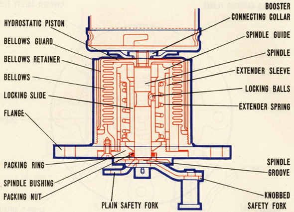
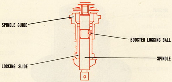
41. The spindle, which extends outward through a bushing in the center of the flange when the mechanism is in the unoperated position, is secured to the inner surface of the piston. An extender sleeve is secured to the inner side of the spindle bushing, and the spindle guide is mounted inside the inner end of the sleeve. The locking slide is installed between the spindle guide and the spindle, and an extender spring is placed between the spindle guide and the locking slide. This spring and the normal tension of the bellows hold the mechanism in the unoperated position until hydrostatic pressure is applied to it. |
|
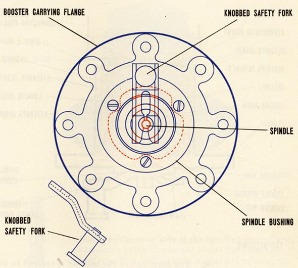
42. The outer end of the spindle, which projects through the spindle bushing is grooved to take the safety fork which locks the mechanism safe prior to use. A plain fork is used during shipment and storage and when the charge is fired from projectors. This is repla-ced by a knobbed fork when a depth charge is placed in a release track. |
|
|
|
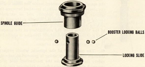
43. Locking balls are fitted in the locking slide of the mechanism. In the safe position these balls fit in a groove in the spindle and are held there by the spindle guide. |
|
|
|
LOCKING BALLS AND LOCKING SLIDE |
|
|