|
|
|
ALLIED BOMBS AND FUZES |
| BRITISH FUZES |
|
FUZE DATA |
FILE NO.: 2214.T20 |
|
NATIONALY: BRITISH |
INFORMATION DATE: February 1944 |
|
DESIGNATION |
PRINCIPAL MARKING |
|
|
Fuze No. 848 |
CLASSIFICATION |
Fuze, Aerial Burst, Pyrotechnic |
|
Mks. I & II |
TYPE OF MISSILE |
Flare |
|
MARKINGS: |
|
BOMBS USED IN: |
|
|
4.5 inch Photographic Flare. |
|
|
|
4.5 inch Reconnaissane Flare Mks I - IV. |
|
|
4.5 inch Target Flare Mk I. |
||
|
|
4.5 inch Reconnaissance Flare Mks I & II. |
|
|
|
|
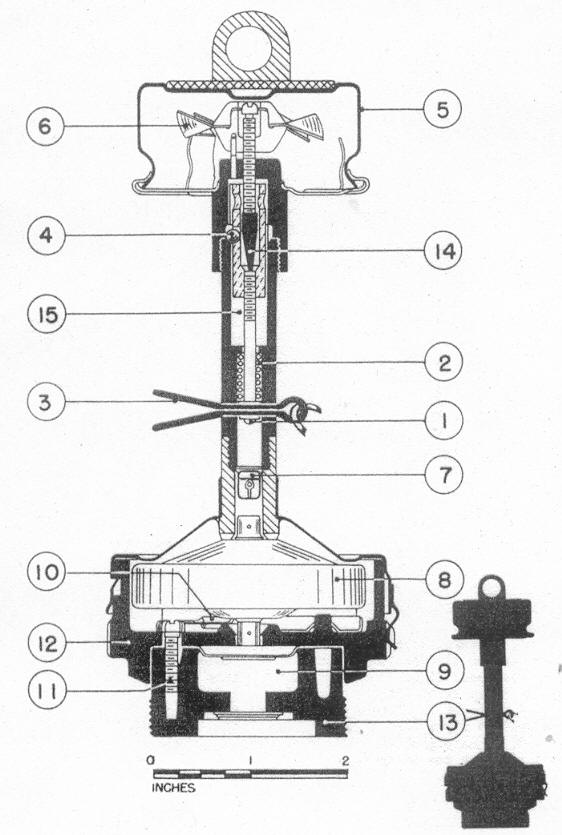
LEGEND |
|
1 |
Striker |
9 |
Burster |
|
2 |
Striker spring |
10 |
Safety shutter |
|
3 |
Cotter key |
11 |
Screw |
|
4 |
Retainer balls |
12 |
Body |
|
5 |
Vane cover |
13 |
Base plug |
|
6 |
Vanes |
14 |
Arming spindle |
|
7 |
Primer |
15 |
Sleeve |
|
8 |
Delay capsule |
|
COLOR |
Unpainted steel. |
|
OVERALL LENGTH |
7.25 inches. |
|
OVERALL WIDTH |
3.0 inches. |
|
MATERIAL OF CONSTRUCTION |
Steel. |
|
DESCRIPTION |
|
The fuze body (12) is secured to the base plug (13) is which the burster (9) is located by means of three screws (11). A dome-shaped cover is attached to the body by a bayonet joint. The striker tube screws into the cover. An arming vane cover (5) is fixed to the end of this tube. The vanes (6) are keyed to a spindle (14) with a cone-shaped tip. This tip extends into a sleeve (15) in which retainer balls (4) are lodged. These balls bear against slots in the striker tube and against the cone of the arming spindle (14). The striker spindle screws into the lower end of the sleeve. A spring (2) bears against the striker head and is compressed against a shoulder of the tube. A safety pin (10) projects through the striker head. Beneath the striker lies the primer (7). The de-lay capsule (8) lies the cover and the body (1). |
|
OPERATION |
|
The cotter key (3) is removed when the flare is loaded. When the flare is released, the vane cover (5) is pulled off and the arming vanes (6) rotate until they lock against the head of the spindle (14). The vanes then cause the spindle to rotate, which release the cone-shaped spindle top. The retainer balls fall inward when the cone has risen sufficiently, and the spring-laoded striker is released. The primer sets off the explosive train. |
|
POSITION & METHOD OF FIXING IN BOMB |
Screwed into the nose of the flare by six right-hand threads. |
|
COMPONENTS OF EXPLOSIVE TRAIN |
Primer, delay and burster. |
|
FUZES LIKELY TO BE FOUND WITH |
None. |
|
REMARKS |
|
1. Delay capsule are supplied for various delays of 3,000 to 20,000 feet of fall after re-lease. |
|
2. The Mk II & II N use is for the Navy Air Arm. It has a sealing band to cover the cot-ter key hole and seal the fuze against moisture. |
|
3. The safety shutter and spring close the flash channel if the delay is not in place. |
|
|