|
|
|
ALLIED BOMBS AND FUZES |
| BRITISH FUZES |
|
FUZE DATA |
FILE NO.: 2214.N2 |
|
NATIONALY: BRITISH |
INFORMATION DATE: March 1944 |
|
DESIGNATION |
PRINCIPAL MARKING |
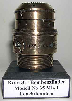
No. 35 Mark I or II |
|
No. 35 Mark |
CLASSIFICATION |
Mechanical Nose Pyrotechnic |
|
I or II |
TYPE OF MISSILE |
Flare |
|
MARKINGS AND |
|
BOMBS USED IN: |
|
SUBSIDIARY |
|
This fuze is for use in flares. |
|
MARKINGS: |
|
|
|
|
|
OPERATION |
|
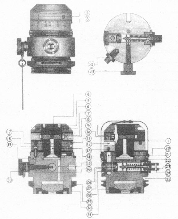
When the flare is released, the firing plug (23) is withdrawn from the retaining plug (22) by the fuze setting link which remains attached to the carrier. Withdrawal of the firing plug causes the striker (21) to be drawn back against its spring until the 2 balls (25) are clear of the retaining plug. The balls then fall outwards, freeing the striker and allowing it to move forward under the action of its spring to fire the detonator (26). The flash from the detonator ignites the powder pellet (27) which blows out the brass es-cape hole disc, allowing flash to pass through a hole (20) in the body of the fuze; this ignites the fuze composition in the lower groove (13) of the time ring, which burns in a clockwise direction. After the safety delay period, the powder pellet (17) ommunicating with upper groove (12) is ignited and its flash blows out the escape hole strip (18) igniting the fuze composition in the upper groove (12), which burns around in a counter-clockwise direction. After an interval of time determined by the position of the setting ring (8), the powder pellets (9) in the setting ring are fired, the flash passing around the annular groove to ignite the powder pellet (7) in the spigot (4). The flash from these pellets passes down the firing channels (14) and (15) and ignites the contents of the magazine (31). When the setting ring (8) is in the SAFE position, the powder pellets (9) are masked and cannot be ignited by the burning composition in the upper groove (12) of the fixed ring. Thus the fuze will be blind if it is set in the SAFE position when the flare is dropped, even through the aircraft fuze setting control is moved to LIVE. |
|
1 |
COLOR |
|
|
2 |
OVERALL LENGTH |
|
|
3 |
OVERALL WITDH |
|
|
4 |
MATERIAL OF CONSTRUCTION |
|
5 |
DESCRIPTION |
|
This fuze consists of a time ring containing two grooves of pressed fuze composi-tion, a rotatable setting ring, used to set the desired delay period, a mechanism for igniting the train of fuze composition, and a magazine for igniting the ejection charge of the flare. The time ring, which is mounted on a spigot screwed into the upper portion of the fuze body, is graduated from 3½ to 17, each graduation re-presenting the burning for approximately one second of the delay composition; a red pointer marked SAFE is also engraved on the ring. When the setting ring is turned to SAFE, the powder pellets (9) are completely masked. |
|
|
The position of safety or a particular delay period may be set by making the red arrow engraved on the rotatable setting ring correspond with the proper marking or graduation on the time ring. |
|
|
The mechanism for igniting the train of fuze composition consists of a spring loa-ded striker (21) and a 1.7 grain detonator pellet (26). Two steel balls (25) are lo-cated in holes in a firing plug (23) which is fitted over the outer end of the striker. These balls engage in a groove in the striker and prevent it from moving forward onto the detonator until the firing plug is withdrawn and the balls frees. The stri-ker and firing plug assemblage are retained in the SAFE position by a safety pin (33) which is screwed into the fuze body and engages in a groove between the two flanges at the head of the striker. A closing plug (32) is screwed into a blind hole in the fuze body. The safety pin is unscrewed after the flare is attached to the plane, and the closing plug is screwed into the hole vacated by the safety pin to exclude moisture. |
|
6 |
POSITION AND METHOD OF FIXING IN BOMB |
Screwed into the nose and secured by a locking ring. |
|
7 |
FUZES LIKELY TO BE FOUND WITH |
None. |
|
8 |
COMPOSITION OF EXPLOSIVE TRAIN |
|
|
9 |
ARMING TIME |
|
10 |
REMARKS |
|
|
1. The No. 35 Mark I fuze is intended primarily for use as an alternative to fuze, time, aircraft flare, nose, No. 28A, B or D. |
|
|
2. It differs from Fuze No. 28 Mark II A, B or D mainly with respect to the safety devices and waterproofing arrangements. |
|
|
3. The necessary period of safety, after the release of the flare, is ensured by a fixed minimum time of delay, 3½ seconds; the maximum setting is 17 seconds. No arming vane mechanism is included. |
|
|
4. The fuze is capable of being dropped safe in an emergency. This is achieved in the usual way, by releasing the flare while the airplane cockpit fuze setting con-trol is in the SAFE position. |
|
|
5. The No. 35 Mark I fuze is obsolete. |
|
|
6. The No. 35 Mark II is similar in design and use to the No. 35 Mark I except that the time rings are filled a powder having a slower rate of burning, so that a longer maximum delay is obtained. |
|
|
7. The graduation on the time ring of the No. 35 Mark II are in terms of hundreds and thousends of feet drop of the 4.5 inch reconnaissance flare, on the assump-tion that the fuze is set so that the flare will function at a height of 3000 feet above sea level. Tables of fuze settings are, therefore, not necessary with this fuze. The fuze admits of a maximum delayed drop of 5500 feet with the 4.5 inch flare. |
|
|
|
|