|
|
|
ALLIED BOMBS AND FUZES |
| BRITISH FUZES |
|
FUZE DATA |
FILE NO.: 2213.N10 |
|
NATIONALY: BRITISH |
INFORMATION DATE: March 1944 |
|
DESIGNATION |
PRINCIPAL MARKING |
|
|
Nose Fuze |
CLASSIFICATION |
Fuze, Nose, Mechanical Long Delay |
|
No. 880 Mk I |
TYPE OF MISSILE |
Small H.E. or A.P. Bombs |
|
MARKINGS: |
|
BOMBS USED IN: |
|
|
|
Small H.E. or
A.P. Bombs |
|
|
|
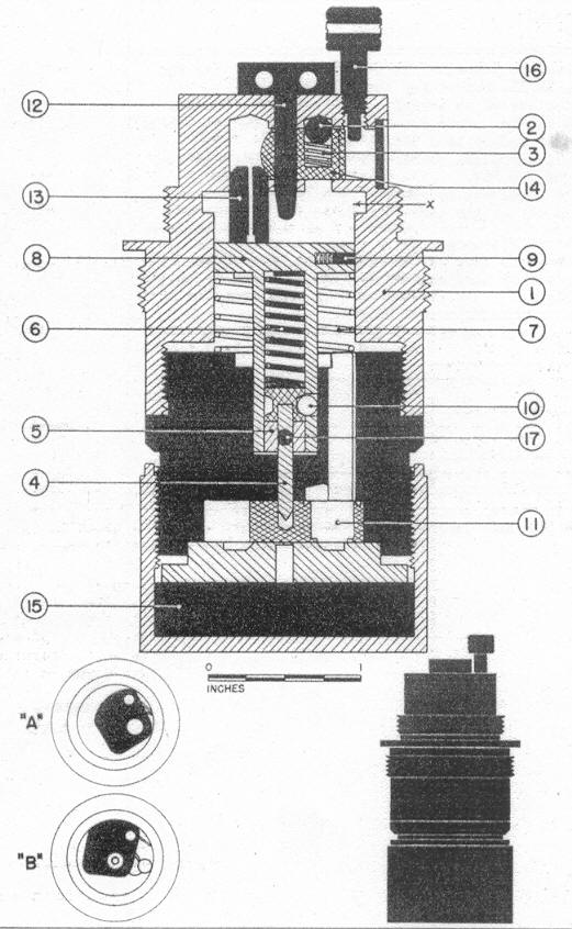
LEGEND |
|
1 |
Body |
9 |
Spring loaded pin |
|
2 |
Steel ball |
10 |
Steel balls |
|
3 |
Spring |
11 |
Primer-detonator |
|
4 |
Striker point |
12 |
Safety pin |
|
5 |
Striker body |
13 |
Inertia weight |
|
6 |
Striker spring |
14 |
Slider block |
|
7 |
Inertia block spring |
15 |
Detonator-booster |
|
8 |
Inertia block |
16 |
Screw plug |
|
COLOR |
Brass. |
|
OVERALL LENGTH |
4.0 inches (about 1.0 inch is visible.) |
|
OVERALL WIDTH |
2.1 inches maximum. |
|
DESCRIPTION |
|
The brass fuze contains a mechanism which gives a long delay by means of the "lead creep" princible. The upper section of the body contains the inertia weight (13) which bears against a safety slider-block (14). The slider-block (14) serves the purpose of preventing the inertia weight from moving toward the top of the fuze. The slider-block is held in place by a spring-loaded ball (2) and by the safety pin (12) which must be remo- ved in order for the fuze to function. A screw plug (16) must also be removed. The inertia block (8) which bears against the inertia weight (13), due to the action of spring (7), contains the striker spring (6), the striker balls (10) and the striker (5). The striker is held in place by a lead wire (17), were it not for the three symmentrically lo-cated steel balls (one is shown at (10)), the striker spring (6) would cause the striker (5) to bear at all times against the lead wire (17). However the force of the striker spring first tends to drive the steel balls (10) outward. Since these balls are not free to drive the steel balls (10) outward. Since these balls are not free to move outward, no pressure is exerted on the lead creep wire (17) when the fuze is unarmed. The primer-detonator (11) and booster (15) are contained in the lower part of the fuze. |
|
OPERATION |
|
The screw plug (16) must be removed after the bomb is loaded in the plane. On re-lease, the safety pin (12) is removed. On impact, the inertia weight (13) moves toward the top of the fuze against the resistance of the slider-block (14), which moves to the right side of the fuze. At the same time, inertia block (8) moves toward the top of the fuze and is locked by the little spring-loaded pin (9) moving into the cavity at (X). As the inertia block (8) moves up, the steel balls (10) and striker are carried with it. As the striker point (4) moves, the spring-loaded detonator-carrier is released and carries the detonator cap from the position shown at "A" to the position shown at "B". The de-tonator cap is then in direct line with the striker. When the inertia block (8) is locked in place the balls (10) are free to move out under action of spring (6). When this occurs, the spring exerts pressure on the lead wire (17). After several hours, depending on the temperature, the lead wire finally shears, and the striker is driven downwards into the primer. |
|
POSITION & METHOD OF FIXING IN BOMB |
The fuze is screwed into the nose of the bomb. |
|
COMPONENTS OF EXOLOSIVE TRAIN |
Primer-detonator (11) and booster (15) |
|
FUZES LIKELY TO BE FOUND WITH |
|
|
DELAY TIMES |
In the fuzes examined, the delay was approximately six hours at 70 degrees F. |
|
|