|
|
|
ALLIED BOMBS AND FUZES |
| BRITISH FUZES |
|
FUZE DATA |
FILE NO.: 2211.T5 |
|
NATIONALY: BRITISH |
INFORMATION DATE: March 1944 |
|
DESIGNATION |
PRINCIPAL MARKING |
|
|
Fuze No. 30 Mk I |
CLASSIFICATION |
Mechanical Tail Time |
|
Fuze No. 37 Mk I |
TYPE OF MISSILE |
S.A.P. - H.E. Bombs |
|
MARKINGS: |
No. 30 Mk I |
BOMBS USED IN: |
|
|
|
250 lb. S.A.P. Mark II |
|
|
|
500 lb. S.A.P. Mark II |
|
|
|
Data |
No. 30 Mk I |
No. 37 Mk I |
|
COLOR |
||
|
OVERALL LENGTH |
||
|
OVERALL WIDTH |
||
|
MATERIAL OF CONSTRUCTION |
|
DESCRIPTION |
|
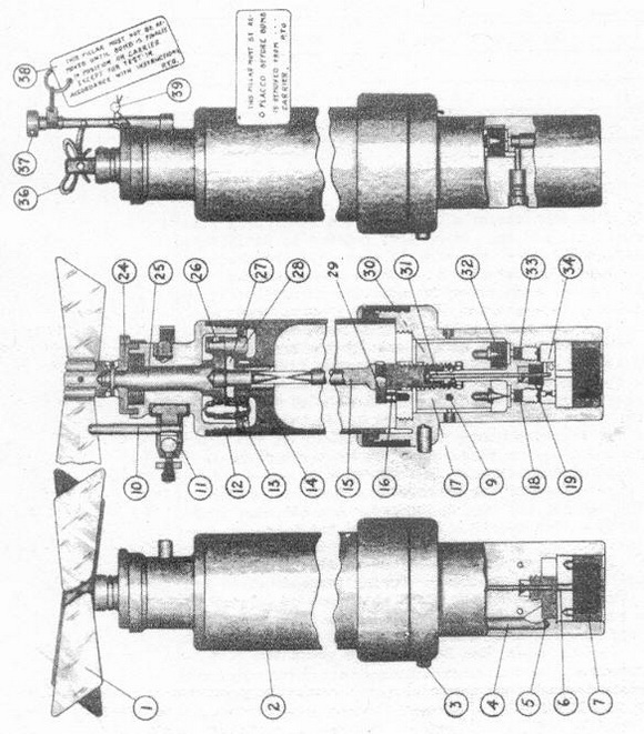
This fuze consists of a body in which are housed the arming and delay assemblies. The arming assembly is fitted into upper end of fuze body and in- volves a system of reduction gears wherein the teeth of the pinion (13) on the lower end of the arming vane spindle (25) engage with the teeth of two other gears (14) and (27). This as-sembly gives a ratio of 60 turns of the ar- ming vanes for one turn of the arming spindle (15) which is being screwed out of inertia weights. The arming vane mechanism is pre-vented from jaming by stop pins (16) and (29). |
|
The delay assembly consists of a long and a short delay mechanism, the long delay consisting of an inertia pellet being held away from the cap only by a creep spring in order that, on slight impact, the weight would compress the spring and detonate the cap. |
|
The short delay mechanism also has an inertia weight, but a shear wire prevents it from moving down. This mechanism is so designed that the bomb must strike a one inch mild steel plate at a velocity of 500 feet per second before wire will be sheared to allow inertia weight to detonate the cap. |
|
Safety Devices:– Safety pillar (38) and safety wires (36) and (39) make the fuze safe for transit. These are removed before bomb is placed in carrier. Arming vane stop (10) and safety clip (11) keep arming vanes from rotating during flight. |
|
Operation |
|
When the bomb is released, the vane stop (10) and safety clip (11) remain attached to the carrier and the arming vanes are free to rotate. The arming vanes, working through the reduction gear described (see Description), cause the arming spindle (15) to be slowly drawn upwards out of the inertia weight and through the rotatable gear wheel (27) in which it is a sliding fit. This frees the two inertia pellets (17) and (30) and also withdraws the lock- ing rod (31) until 5 grain detonator (5) is immediately over the stammed fire channel (6). The shutter is automatically locked in this position by a pawl (22) which is actuated by spring (23) and the fuze is now armed. |
|
On impact, the long delay mechanism will always work, while the short delay will not operate unless certain armored structures are hit. The flash from the cap on detonator ignites a delay fitting, this in turn firing a 5 grain detonator which fires the magazine. |
|
POSITION & METHOD OF FIXING IN BOMB |
Held in place in tail by locating pin and locking ring. |
|
FUZES LIKELY TO BE FOUND WITH |
|
REMARKS |
|
1. The fuze is used in bombs for attacking surface craft. |
|
2. The fuze includes both long and short delay mechanisms, also a geared arming vane safety mechanism which is designed to keep the fuze safe for the first 50 feet of free flight when released at an air speed of 100 miles per hour, but just to permit functioning in 300 feet at that speed. |
|
3. The fuze is capable of being dropped safe in an emergency. This is achieved in the usual way by releasing the bomb while the fuzing rod of the carrier is in SAFE position. |
|
4. The fuze is not capable of giving direct action. |
|
5. The fuze No. 37 Mk I is similar in construction and operation to the No. 30 Mk I. It differs only in length and in the construction of the arming spindle, which has two uni-versal joints due to its added length. |
|
|