|
|
|
ALLIED BOMBS AND FUZES |
| BRITISH FUZES |
|
FUZE DATA |
FILE NO.: 2211.T2 |
|
NATIONALY: BRITISH |
INFORMATION DATE: October 1942 |
|
DESIGNATION |
PRINCIPAL MARKING |
No. 12 Mark I |
|
No. 12 |
CLASSIFICATION |
Mechanical Tail Impact |
|
Mark I |
TYPE OF MISSILE |
Used only in tail of Bomb, Aircraft, |
|
|
H.E.S.N. Mark II |
|
|
MARKINGS AND |
|
BOMBS USED IN: |
|
SUBSIDIARY |
|
Used only in tail of Bomb, Aircraft, |
|
MARKINGS: |
|
H.E.S.N. Mark II |
|
|
|
|
DATA |
No. 12 Mark I |
|
1 |
COLOR |
Brass. |
|
2 |
OVERALL LENGTH |
20.5 inches (less booster). |
|
3 |
OVERALL WIDTH |
2.0 inches. |
|
4 |
DIAMETER OF |
7.5 inches (six blades). |
|
5 |
MATERIAL OF CONSTRUCTION |
Body tube and striker steel. Collar and arming vanes - brass. |
|
6 |
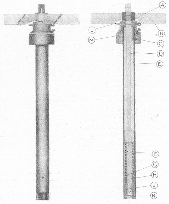
DESCRIPTION |
The fuze consists of a steel tube (E) with the lower portion threaded to screw into adapter of an exploder. A bushing is pressed into lower end of tube to act as guide for striker. There are four gas grooves (H) and gas escape holes (G). The top portion of the tube (E) screws into the brass body collar (M). The brass collar (M) is threaded internally to screw over the central tube of the bomb, and to receive the steel tube (E). The collar (M) has a groove cut in its top surface for the head of the arming vanes stop screw (A). The striker rod (D) is made of steel and its lower end terminates in the striker (J). There is a collar about half way up the striker rod (D) which serves as a base for the creep spring (F). The top of the striker rod (D) is threaded to take the arming vanes (B). The arming vanes (B) consist of six cast brass blades, with a stop screw (A) fixed to the under side of the vane boss. |
|
|
Safety Devices:– There is a safety pin (L) which passes through the brass collar (M) and the striker rod (D). The striker rod spring (F), fits between the top of the striker guide bushing and the collar on the striker rod. The arming vanes (B) have a safety pin clip which prevents their rota- tion and/or loss during the flight of the plane. |
|
|
7 |
POSITION AND METHOD OF FIXING IN BOMB |
Screwed into the end of the central exploder tube of the bomb and held in place by a set-screw. |
|
8 |
FUZES LIKELY TO BE FOUND WITH |
Nose: No. 13 Mark I. |
|
9 |
COMPONENTS OF EXPLOSIVE TRAIN |
Detonator No. 9 Mark I, Exploder H.E. Bomb 34.8 inches, No. 11 Mark I. |
|
10 |
ARMING TIME |
|
|
11 |
OPERATION |
When the bomb is released from the plane, the fuzing wire is with-drawn. This removes the safety pin clip and the ar- ming vanes are then unscrewed by the action of the air. The fuze is then armed and on impact the plunger is carried into the bomb by its own momentum, compressing the spring and allowing the striker to hit the cap in the cartrid-ge head of the detonator. |
|
12 |
REMARKS |
The arming vanes unscrew and fall clear. |
|
|