|
|
|
ALLIED BOMBS AND FUZES |
| BRITISH FUZES |
|
FUZE DATA |
FILE NO.: 2211.N85 |
|
NATIONALY: BRITISH |
INFORMATION DATE: February 1944 |
|
DESIGNATION |
PRINCIPAL MARKING |
|
|
Fuze No. 866 |
CLASSIFICATION |
Fuze, Nose, Mechanical Impact |
|
Mk I |
TYPE OF MISSILE |
Anti-Submarine Bombs |
|
MARKINGS: |
|
BOMBS USED IN: |
|
|
|
35 lb. Anti-Submarine Bombs, |
|
|
|
Mk I and Mk II |
|
|
|
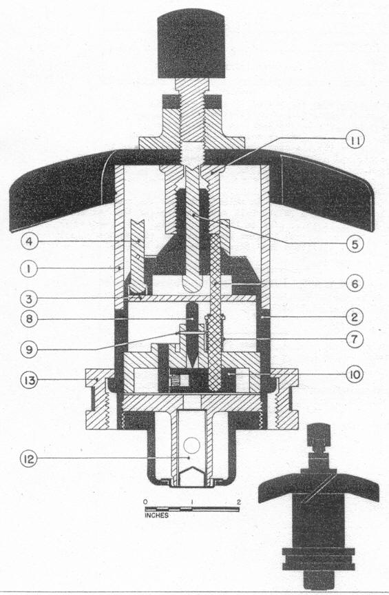
LEGEND |
|
1 |
Upper portion of body |
8 |
Striker |
|
2 |
Lower portion of body |
9 |
Shear wire |
|
3 |
Circular plate |
10 |
Threaded carrier |
|
4 |
Prong |
11 |
Threaded collar |
|
5 |
Central prong |
12 |
Booster |
|
6 |
Detent |
13 |
Locking ring |
|
7 |
Detent spring |
|
COLOR |
Black top; brass bottom. |
|
OVERALL LENGTH |
5.25 inches. |
|
OVERALL WIDTH |
1.62 inches (Body); 4.0 inches (Vanes). |
|
MATERIAL OF CONSTRUCTION |
Plastic and Brass. |
|
DESCRIPTION |
The upper portion (1) of the body is made of a plastic material which will be crushed on impact. The lower portion (2) is made of brass. It contains three symmetrically arranged prongs (one of which is shown at (4).) which are held in place by a shear wire. A fourth prong is centrally located (5). All prongs bear against a circular plate (3) which rests on top of the striker (8). The shear wire (9) holds the striker (8) in place. A spring-loaded detent (6) passes through the circular plate (3). The lower end of the detent engages the spring-loaded detonator carrier (10). Bearing down on the upper end of the detent is the arming vane threaded collar (11). When the arming vanes are in the unarmed position, as shown, the detent spring (7) is compressed and the detent (6) engages the detonator carrier (10) and keeps the detonator out of line with the striker (8). |
|
OPERATION |
On release from the airplane, the arming wire is withdrawn, thereby allowing the vanes to rotate and fall free after eight revolutions. As the vanes rotate, the arming vane assembly moves upward, allowing the detent (6) to move upwards to-wards the top of the fuze under action of the detent spring (7). This frees the detonator carrier (10) which swings over and places the detonator directly under the striker. On impact with the submarines, the plastic upper portion of the body (1) is crushed, thereby driving the prongs (4) and (5) against the cir-cular plate which in turn bears down on the striker (8), shearing the wire (9) and driving the striker into the detonator. |
|
POSITION & METHOD OF FIXING IN BOMB |
The fuze is inserted in the nose and held in place by a locking ring (13). |
|
COMPONENTS OF EXPLOSIVE TRAIN |
Primer-detonator, and small booster. |
|
FUZE LIKELY TO BE FOUND WITH |
|
|
DELAY TIMES |
None. |
|
ANTI-WITHDRAWAL |
None. |
|
REMARKS |
The British refer to this as the "TRIDENT" fuze because of the three prongs located in the fuze body. For details of the deto-nator carrier, see the information pages on the Nose Fuze No. 880. |
|
|