|
|
|
ALLIED BOMBS AND FUZES |
| BRITISH FUZES |
|
FUZE DATA |
FILE NO.: 2211.N4 |
|
NATIONALY: BRITISH |
INFORMATION DATE: October 1942 |
|
DESIGNATION |
PRINCIPAL MARKING |
D.A. No. 16 Mark I |
|
D.A. No. 16 |
CLASSIFICATION |
Mechanical Nose Impact |
|
Mark I |
TYPE OF MISSILE |
Bomb Aircraft, H.E.R.L. 20 lb. Mk. I |
|
MARKINGS AND |
|
BOMBS USED IN: |
|
SUBSIDIARY |
|
This fuze may only be used with Bomb, |
|
MARKINGS: |
|
Aircraft, H.E.R.L. 20 lb. Mark I. |
|
|
|
OPERATION |
|
|
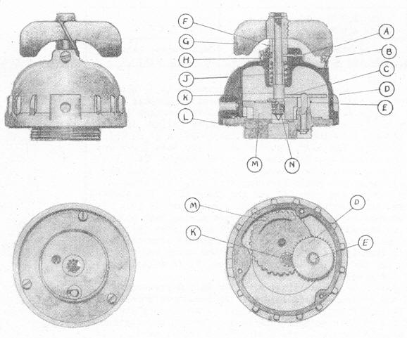
When the bomb is on the carrier, the arming vanes are prevented from rotating by the arming vane stop. The normal setting for the striker pellet gear wheel is when the number "25" is visible through the body plate hole. On release of the bomb, the arming vanes rotate and acting through the intermediate gear wheel, cause the striker pellet gear wheel to revolve. After approximately 25 revolutions of the arm-ing vanes, the stop (C) on the upper surface of the striker pellet gear wheel (M) comes into contact with the lower end of the plunger (E). At the same time, the small diameter gear wheel (E) is brought opposite the cut away portion of the stri-ker pellet gear wheel (M). On impact, the arming vanes, plunger, and guide bush are driven inwards, thus breaking the shearing wire (A). At the same time, the plunger spring is compressed. The inner end of the plunger is brought into forcible contact with the striker pellet, and drives it inwards onto the cap of the detona-tor. |
|
|
DATA |
D.A. No. 16 Mark I |
|
|
1 |
COLOR |
Brass |
|
|
2 |
OVERALL LENGTH |
3.3 inches (less booster) |
|
|
3 |
OVERALL WIDTH |
Body 3.1 inches (approx.) |
|
|
4 |
MATERIAL OF CONSTRUCTION |
Arming vanes aluminum, gear train brass and plunger brass. |
|
|
5 |
DESCRIPTION |
|
|
Body plate (L) is threaded on its rear surface to screw into the nose of the body, and bored centrally to allow the striker pellet (N) to move on to the cap of the detonator. The striker pellet gear wheel (M) is attached to top of plate (L) and engages with the intermediate gear wheels (D) and (E) which are of two different diameter. Gear wheel (M) is toothed on the greater part of its circumference and the remaining part is cut away. The triangular stop (C) is formed on its upper sur-face at one end of the gear teeth. Adjacent to this stop is the hole in which the striker pellet (N) is housed. The under surface of the gear wheel (M) is engraved with the members 5, 10, 15, 20, and 29 at the same radius as the striker pellet hole. The intermediate gear wheel consists of a small gear (E) which engages with striker pellet gear wheel (M), and a large diameter gear wheel (D) which engages with the plunger gear wheel (E). The body dome is attached to plate (L) with three screws. At the top dome is a vertical hole for the guide bushing (F). The plunger is brass and hase five aluminum vanes rivetted to the plunger. The guide bushing (F) is held in place by a grub screw (H) and shearing wire (A), and the plunger is free to revolve in this guide. The lower end of the plunger (K) is toothed to engage with the large diameter intermediate gear wheel (D). |
|
|
Safety Devices: - The shear wire (A) passes through the dome and the plunger guide (F). Until the gear wheel (M) has been moved so that the striker pellet (N) lies directly under the plunger (F) and (K), it is impossible for the striker pellet to move onto the cap of the detonator. Approximately 25 revolutions of the arming vanes (G) are necessary to bring the hole in the striker pellet gear wheel over the hole in the body plate. One of the arming vanes has a hole drilled in it, and is se-cured to a lug on the dome by a safety wire (B), for transport only. |
|
6 |
POSITION AND METHOD OF FIXING IN BOMB |
Screwed into nose of bomb. |
|
7 |
FUZES LIKELY TO BE FOUND WITH |
None. |
|
8 |
COMPONENTS OF EXPLOSIVE TRAIN |
Booster fitted separatly in bomb. |
|
9 |
ARMING TIME |
Can be set to arm in 1 - 25 revolutions of vanes. |
|
10 |
REMARKS |
Fuzes must never be used at shorter settings then "25", vi-sible through the body plate hole. |
|
|